
Electro-luminescent display with adjustable white point

Active Publication Date: 2010-11-18
GLOBAL OLED TECH
View PDF12 Cites 48 Cited by
  • Summary
  • Abstract
  • Description
  • Claims
  • Application Information

AI Technical Summary

Benefits of technology

[0020]An advantage of the present invention is that it can produce images with a range of color temperatures in which high power efficiency is provided regardless of display color temperature. This provides the viewer of the display the flexibility of selecting a display color temperature without increasing the power consumption of the display, thereby maintaining high power efficiency. Some arrangements of the present invention have the added advantage that they provide multiple in-gamut light-emitting elements to extend the useful lifetime of the display device.

Problems solved by technology

Although, this method adds cost to the overall LCD system, these displays make relatively efficient use of the light that is produced, as the light source is directly modified to create the color of light that is needed.
Unfortunately, it is not possible to employ adjustable backlights in emissive displays and so this method cannot be applied directly in emissive displays, such as EL displays.
Similar methods are used to adjust the luminance ratio of red, green, and blue emitters in emissive displays, this problem becomes somewhat more complex when additional emitters are added to the display.
However, not all displays have only red, green, and blue emitters.
These methods allow the color temperature of the display to be adjusted, however, they have the disadvantage that they also have a significant effect on the power consumption of the display.
As a result, the power consumption of the display can vary dramatically for displays having four or more emitters as the color temperature of the display is changed.

Method used


Image

  • Electro-luminescent display with adjustable white point
  • Electro-luminescent display with adjustable white point
  • Electro-luminescent display with adjustable white point

Examples


Embodiment Construction

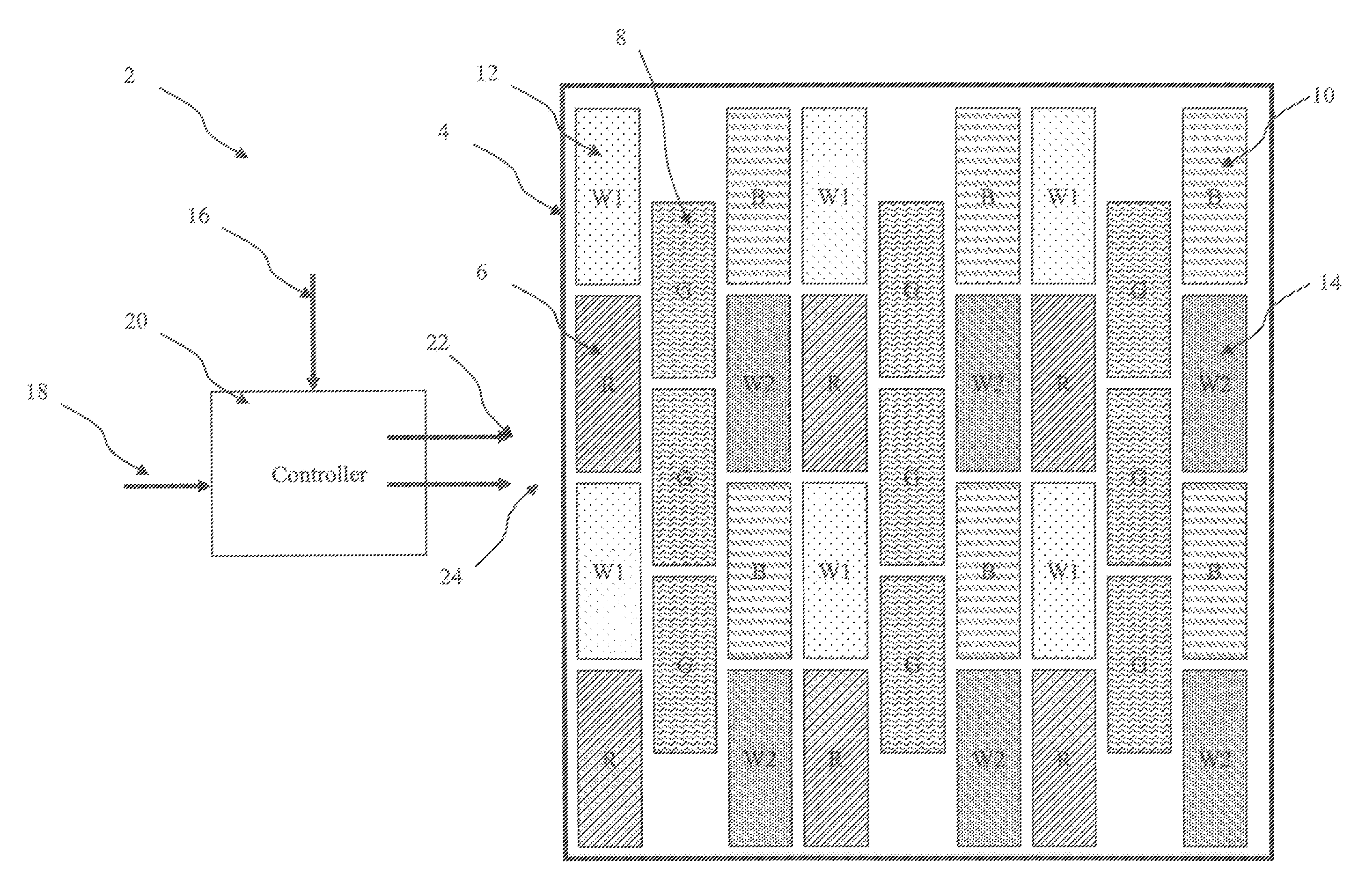
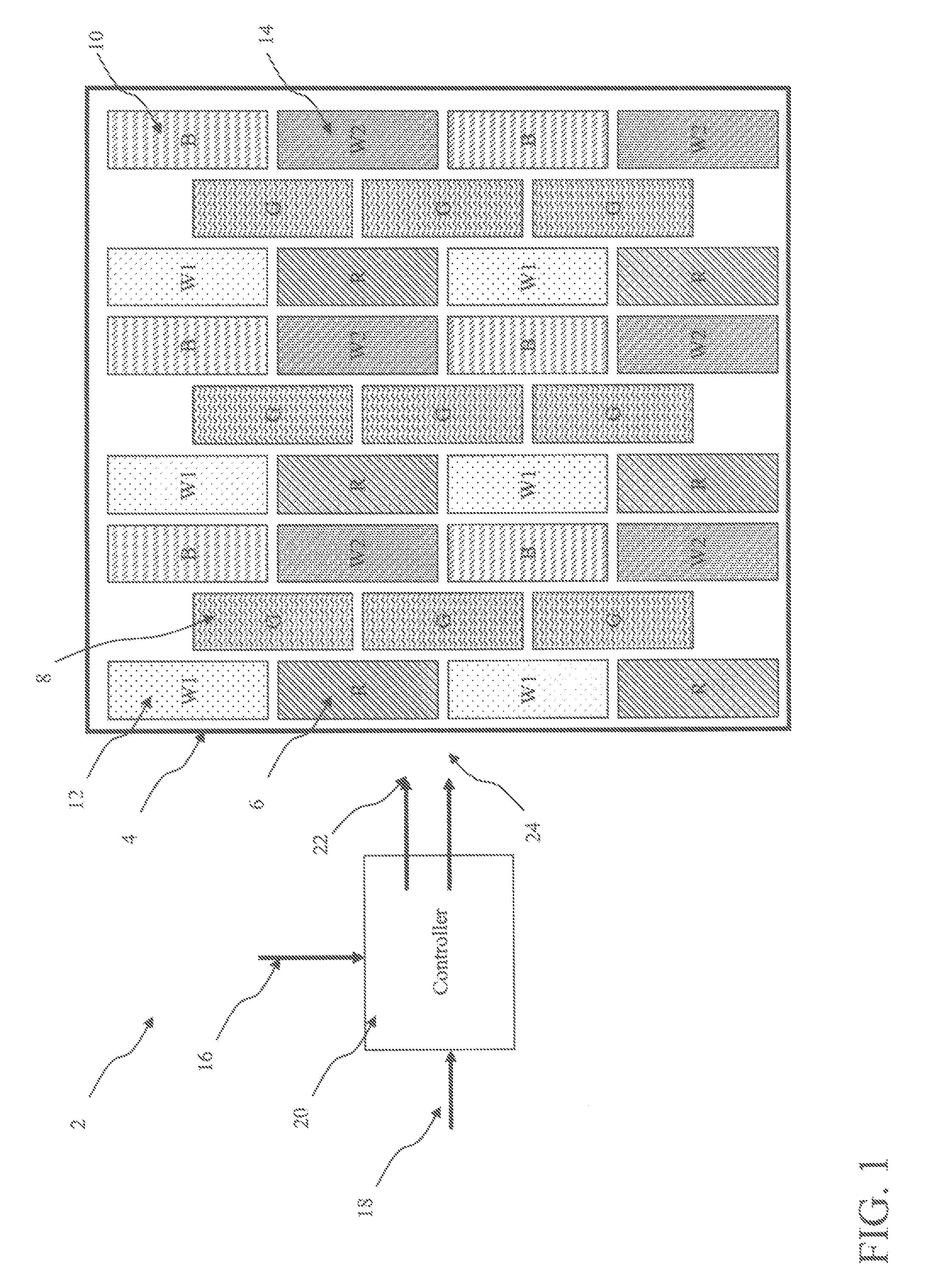
[0036]One arrangement of the present invention provides an EL display 2 adapted to receive a three-color input image signal 18, which includes a display panel 4, including three gamut-defining EL emitters 6, 8, 10 for emitting red, green, and blue colored light, respectively, and a first and a second additional EL emitter 12, 14 for emitting two additional colors of light having chromaticity coordinates specifying two pseudo-blackbody points, the chromaticity coordinates of the two additional colors of light lying inside a gamut defined by the three gamut-defining emitters 6, 8, 10 and near the Planckian Locus, wherein the two pseudo-blackbody points have respective correlated color temperatures that differ by at least 2000 K. Each EL emitter 6, 8, 10, 12, 14 outputs light at a corresponding luminance value in response to a corresponding drive signal. The EL display 2 further includes a way of providing a display white point; and a controller 20 responsive to the provided display wh...


PUM


Abstract

The present invention provides an EL display adapted to receive a three-color input image signal, including three gamut-defining EL emitters for emitting red, green, and blue colored light and two additional EL emitters for emitting at least two additional colors of light, the chromaticity coordinates of the at least two additional colors of light lying inside the gamut and near the Plankian Locus; a structure for providing a display white point; and a controller responsive, to the provided display white point and the input image signal for providing first separate drive signals for the three gamut-defining EL emitters and second separate drive signals for the two additional EL emitters, wherein the respective luminance values corresponding to the second separate drive signals are each a function of the input image signal and the distances between the display white point and the pseudo-blackbody points of the two additional colors.

Description

CROSS REFERENCE TO RELATED APPLICATIONS[0001]Reference is made to commonly-assigned U.S. patent application Ser. No. 12 / 174,085 filed Jul. 16, 2008 entitled “CONVERTING THREE-COMPONENT TO FOUR-COMPONENT IMAGE” to Ronald S. Cok et al., the disclosure of which is incorporated herein.FIELD OF THE INVENTION[0002]The present invention provides an electro-luminescent display apparatus having an adjustable white point. Specifically, an electro-luminescent display apparatus is provided having at least two in-gamut electro-luminescent emitters for emitting two colors of light to provide an adjustable white point, with reduced power consumption.BACKGROUND OF THE INVENTION[0003]Flat-panel display devices are widely used in conjunction with computing devices, in portable devices, and for entertainment devices; including televisions. Such displays typically employ a plurality of pixels distributed over a substrate to display images. Each pixel incorporates several, differently-colored emitters, ...

Claims


Application Information

Patent Timeline
IPC IPC(8): G09G3/30
CPCG09G3/2003G09G3/30G09G3/3208G09G2300/0452H01L51/5265G09G2330/021H01L27/3213H01L27/322G09G2320/0666H10K59/351H10K59/38H10K59/876H10K50/852
Inventor MILLER, MICHAEL E.BOROSON, MICHAEL L.
Owner GLOBAL OLED TECH
Learn More