Battery Thermal Management System

a thermal management system and battery technology, applied in secondary cell servicing/maintenance, batteries, cell components, etc., can solve the problems of battery life significantly decreasing, high-performance batteries exhibiting reduced performance, and possible damag

Active Publication Date: 2010-11-18
GENTHERM INC
View PDF107 Cites 58 Cited by
  • Summary
  • Abstract
  • Description
  • Claims
  • Application Information

AI Technical Summary

Benefits of technology

[0009]In certain embodiments, a battery thermal management system includes at least one battery, at least one thermoelectric device in thermal communication with the at least one battery, and at least one first conduit comprising at least one inlet configured to allow a first working fluid to enter and flow into the at least one first conduit and into thermal communication with the at least one thermoelectric device. The at least one first conduit further comprises at least one outlet configured to allow the first working fluid to exit and flow from the at least one first conduit and away from being in thermal communication with the at least one thermoelectric device. The battery thermal management system can further include at least one first flow control device which directs the first working fluid through the at least one inlet of the at least one first conduit and at least one second flow control device which directs the first working fluid through the at least one outlet of the at least one first conduit. The at least one first flow control device and the at least one second flow control device are each separately operable from one another.
[0010]In some embodiments, the at least one second conduit comprises at least one inlet configured to allow a second working fluid to enter and flow into the at least one second conduit and into thermal communication with the at least one thermoelectric device. The at least one second conduit comprises at least one outlet configured to allow the second working fluid to exit and flow from the at least one second conduit and away from being in thermal communication with the at least one thermoelectric device. The battery thermal management system can also include at least one third flow control device which directs the second working fluid through the at least one inlet of the at least one second conduit and at least one fourth flow control device which directs the second working fluid through the at least one outlet of the at least one second conduit. The at least third first flow control device and the at least one fourth flow control device can each be separately operable from one another.
[0011]In certain embodiments, a method of thermally managing a battery system includes transferring heat between at least one battery and at least one thermoelectric device, and flowing a working fluid through a fluid conduit in thermal communication with the at least one thermoelectric device. The method can also include operating at least one first flow control device to direct the working fluid to be in thermal communication with the at least one thermoelectric device, and operating at least one second flow control device separately from the operating of the at least one first flow control device to direct the working fluid away from being in thermal communication with the at least one thermoelectric device.
[0012]In certain embodiments, a battery thermal management system includes at least one battery, at least one thermoelectric device in thermal communication with the at least one battery, and at least one fluid conduit configured to allow a working fluid to flow therein and to transfer the working fluid into being in thermal communication with the at least one thermoelectric device or away from being in thermal communication with the at least one thermoelectric device. The battery thermal management system can further include at least one first flow control device which directs the working fluid through the at least one fluid conduit and at least one second flow control device which directs the working fluid through the at least one fluid conduit. The at least one first flow control device and the at least one second flow control device are each separately operable from one another. The battery thermal management system can also include at least one divider portion that is selectively positionable to block the working fluid from flowing between the at least one fluid conduit and a selected one of the at least one first flow control device and the at least one second flow control device.
[0013]In certain embodiments, a method of thermally managing a battery system includes transferring heat between at least one battery and at least one thermoelectric device, and flowing a working fluid through a fluid conduit in thermal communication with at least one thermoelectric device. The method can further include directing the working fluid through the fluid conduit using at least one first flow control device and at least one second flow control device, and selectively inhibiting flow of the working fluid through a selected one of the at least one first flow control device and the at least one second flow control device.
[0014]In certain embodiments, a method of thermally managing a battery system includes providing a battery system comprising at least one battery and a plurality of thermoelectric devices in thermal communication with the at least one battery. The plurality of thermoelectric devices comprise a first group of one or more thermoelectric devices in series electrical communication with a second group of one or more thermoelectric devices. The method can further include measuring a first electrical voltage or current of the first group, measuring a second electrical voltage or current of the second group or of both the first group and the second group together, and monitoring an electrical comparison parameter dependent on the first electrical voltage or current and the second electrical voltage or current.

Problems solved by technology

Charging characteristics of high performance batteries change at elevated temperatures and can cause the cycle life of the batteries to decrease significantly if they are charged at too high of a temperature.
Also, some high performance batteries can exhibit reduced performance and can be possibly damaged if charged or operated at too low of temperatures, such as below about −30° C. Furthermore, high performance batteries and arrays of high performance batteries can experience thermal events from which the batteries can be permanently damaged or destroyed, and over temperature condition can even result in fires and other safety related events.

Method used


Image

  • Battery Thermal Management System
  • Battery Thermal Management System
  • Battery Thermal Management System

Examples


Embodiment Construction

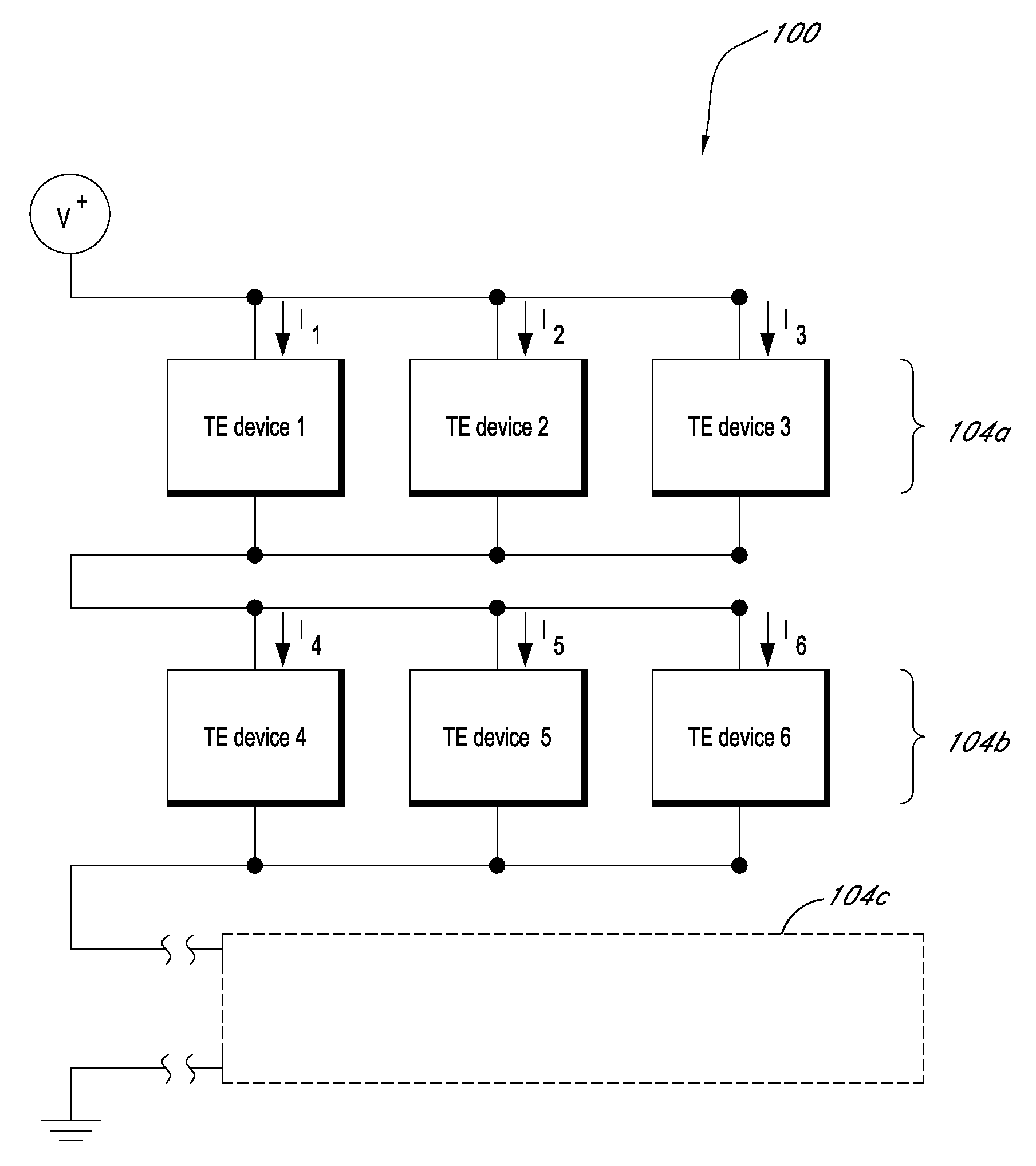
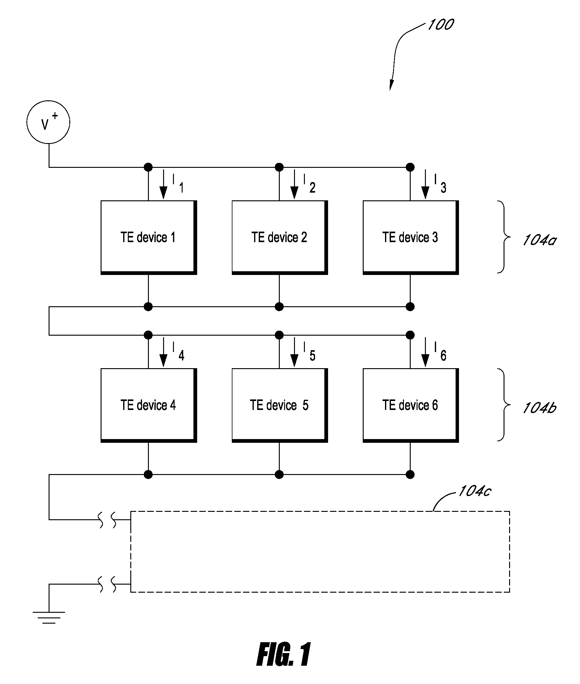
[0023]Battery thermal management systems (BTMS) can be used to control temperatures and monitor conditions of batteries and arrays of batteries to prevent battery failure and / or safety related failure. A BTMS can improve the overall conditions of battery operation by both managing the thermal environment and also being sufficiently reliable so that overall system performance is not degraded. For example, a BTMS may not reduce overall system reliability and not increase system operating cost by not including significant additional possible failure mechanisms to the system. Furthermore, the systems can be environmentally friendly and not contain materials that emit greenhouse gases such as refrigerants.

[0024]A BTMS includes at least one battery or battery array. In certain embodiments, a battery thermal management system can be used to both heat and cool batteries and / or battery arrays. For example, the battery thermal management system can be integrated with the at least one battery,...


PUM

PropertyMeasurementUnit
charging temperaturesaaaaaaaaaa
temperatureaaaaaaaaaa
electricalaaaaaaaaaa

Abstract

In certain embodiments, a battery thermal management system includes at least one battery, at least one thermoelectric device in thermal communication with the at least one battery, and a conduit comprising an inlet configured to allow a working fluid to enter and flow into the conduit and into thermal communication with the at least one thermoelectric device. The conduit further comprises an outlet configured to allow the working fluid to exit and flow from the conduit and away from being in thermal communication with the at least one thermoelectric device. The battery thermal management system can further include a first flow control device which directs the working fluid through the inlet of the conduit and a second flow control device which directs the working fluid through the outlet of the conduit. The first flow control device and the second flow control device are each separately operable from one another.

Description

CROSS-REFERENCE TO RELATED APPLICATIONS[0001]This application claims the benefit of U.S. Provisional Application No. 61 / 179,326 filed May 18, 2009, which is incorporated herein in its entirety by reference.BACKGROUND[0002]1. Field of the Invention[0003]The present application relates to battery thermal management systems and thermoelectric cooling and heating batteries.[0004]2. Description of the Related Art[0005]High performance batteries for use in large systems (including, for example, lithium based batteries used in electrical vehicles) have certain properties that make thermal management of the batteries and / or containment system desirable. Charging characteristics of high performance batteries change at elevated temperatures and can cause the cycle life of the batteries to decrease significantly if they are charged at too high of a temperature. For example, the cycle life of some lithium based batteries decreased by over 50% if they are repeatedly charged at about 50° C. Since...

Claims


Application Information

Patent Timeline
Patent Type & Authority Applications(United States)
IPC IPC(8): H01M10/50B60L50/64H01M50/77
CPCH01M2/1077H01M10/48H01M10/5004Y02E60/12H01M10/5067H01M10/5077H01M10/5085H01M10/5006H01M10/615H01M10/6563H01M10/6568H01M10/6572H01M10/613Y02E60/10H01M50/249B60L50/64H01M10/486H01M50/24Y02T10/70Y02T90/16H01M10/617H01M10/625H01M10/63H01M4/06H01M4/134H01M4/136H01M4/1397H01M6/162H01M10/637H01M2220/20H01M10/61H01M10/653H01M10/6556
Inventor BELL, LON E.LAGRANDEUR, JOHNDAVIS, STEPHEN
Owner GENTHERM INC
Why Eureka
Try Eureka