Facet joint implant

a facet joint and implant technology, applied in the field of facet joint implants, can solve problems such as restrictions on movemen

Inactive Publication Date: 2010-11-18
AESCULAP AG
View PDF5 Cites 13 Cited by
  • Summary
  • Abstract
  • Description
  • Claims
  • Application Information

AI Technical Summary

Benefits of technology

[0024]The width and/or the thickness of the arms can vary over the length thereof. It is thereby possible to adjust the stiffness of the arms to a preferred value and thus produce the desi...

Problems solved by technology

Moreover, the arms limit the movement of the joint surface replacement elements relative to each other so that the latter—mutually abutting—elements ...

Method used


Image

  • Facet joint implant
  • Facet joint implant
  • Facet joint implant

Examples


Embodiment Construction

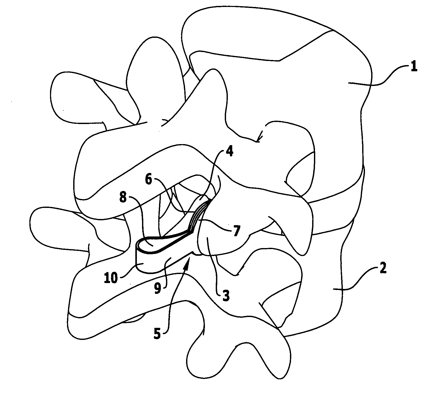
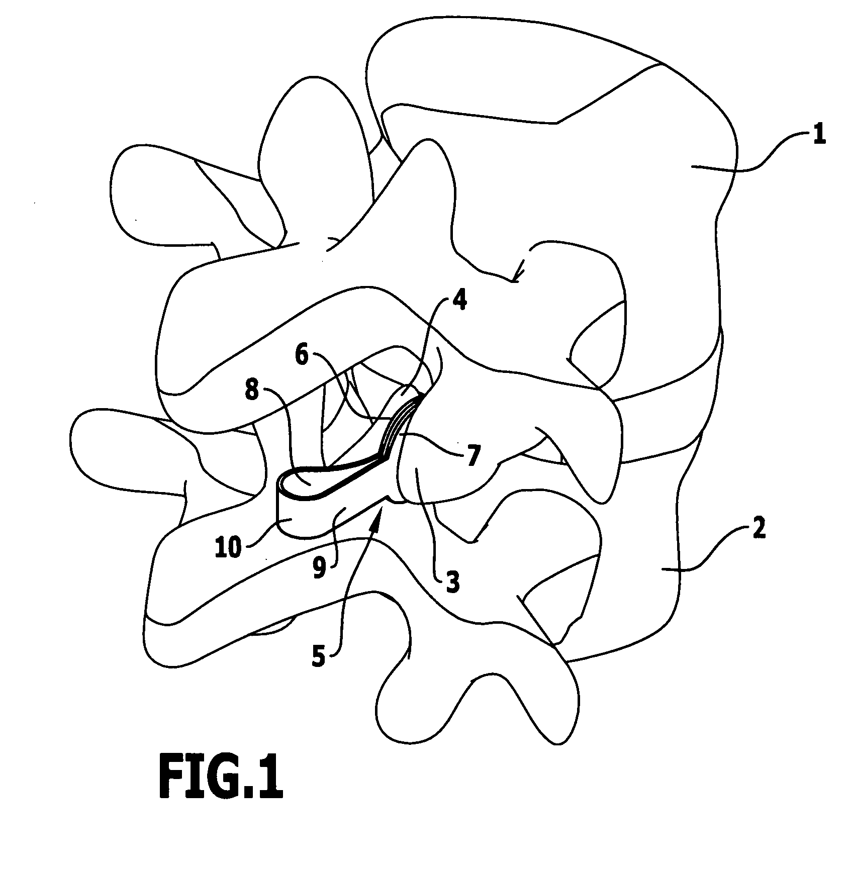
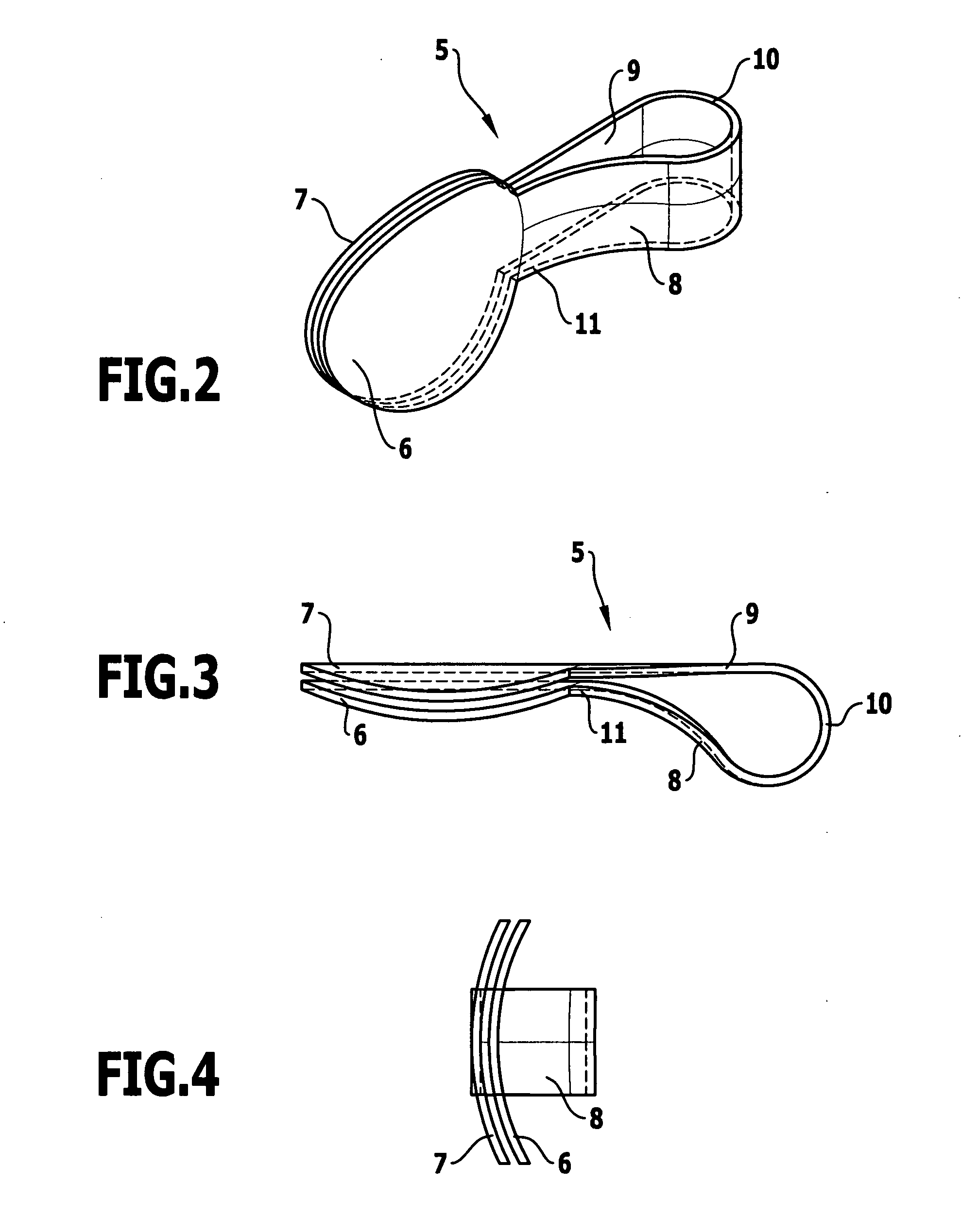
[0045]Two vertebral bodies 1, 2 which are arranged adjacent to one another and comprise respective facets 3 and 4 that rest upon one another are illustrated in FIG. 1. A facet joint implant 5, which comprises two flat joint platelets 6, 7 abutting each other face-to-face, is inserted between the facets 3, 4—if necessary after removal of the joint capsule and / or the cartilage layer of the facets. These joint platelets 6, 7 are fixed in an appropriate manner to the facets 3, 4, for example, by means of projections arranged on the outer surfaces of the joint platelets 6, 7, by means of a tissue glue or with the aid of other known means. The joint platelets 6, 7 are thereby firmly connected to the facets 3, 4 and form a joint replacement surface since the joint platelets 6, 7, which abut each other face-to-face, can be displaced with respect to each other and thereby move with respect to one another substantially parallel to the plane of the joint platelets 6, 7.

[0046]In the embodiment ...


PUM


Abstract

In order to improve the process of inserting a facet joint implant comprising two, flat joint surface replacement elements abutting each other face-to-face and in order to control the movement of the joint surface replacement elements relative to each other, it is proposed that both joint surface replacement elements should carry at least one arm which emerges in the plane of the joint surface replacement element from said element and projects therefrom, and in that in each case two arms of the two joint surface replacement elements which extend adjacent to one another in a pair are connected together at the end thereof remote from the joint surface replacement element.

Description

[0001]This application claims the benefit of German Patent Application No. 10 2009 021 134.9 filed on May 13, 2009.[0002]The present disclosure relates to the subject matter disclosed in German patent application DE 10 2009 021 134.9 of May 13, 2009, which is incorporated herein by reference in its entirety and for all purposes.BACKGROUND OF THE INVENTION[0003]The invention relates to a facet joint implant comprising two flat joint surface replacement elements abutting each other face-to-face.[0004]The facet joints represent one significant cause for the occurrence of back pain. A remedy for this can be obtained by replacing the entire facet joint or by the replacement of the facet joint surfaces after removal of the pain-inducing articular capsules and cartilage layers.[0005]It is known to permanently connect the facets of neighbouring vertebral bodies rigidly together and thus prevent the movement of the two vertebral bodies in the facet joint but, as a consequence thereof, the pa...

Claims


Application Information

Patent Timeline
IPC IPC(8): A61F2/44
CPCA61F2/4405A61F2002/3037A61F2002/30462A61F2002/30467A61F2002/30563A61F2002/30566A61F2220/0083A61F2002/30601A61F2002/30662A61F2002/30841A61F2220/0033A61F2220/0075A61F2002/30571
Inventor LINDNER, STEPHANHAAS, ALEXANDERKETTENBERGER, ULRIKE
Owner AESCULAP AG
Why Eureka
Try Eureka