
Nail gel solidification apparatus

a solidification apparatus and gel technology, applied in lighting and heating apparatus, drying machines, furnaces, etc., can solve the problems of shortening the life of the control circuit, increasing the resistance in the circuit, and increasing the cost of the lamp, so as to shorten the solidification time and reduce the cos

Inactive Publication Date: 2010-11-25
CHANG PAO MIN
View PDF7 Cites 45 Cited by
  • Summary
  • Abstract
  • Description
  • Claims
  • Application Information

AI Technical Summary

Benefits of technology

[0004]In view of the aforementioned shortcomings of the conventional nail gel solidification apparatus, the inventor of the present invention based on years of experience in the related industry to conduct extensive researches and experiments, and finally developed a nail gel solidification apparatus, in hope of achieving the effects of providing an application for hands and feet, shortening the solidification time, and lowering the cost.
[0006]Therefore, the nail gel solidification apparatus of the present invention definitely can achieve the effects of providing an application for hands and feet, shortening the solidification time, and lowering the cost.

Problems solved by technology

However, the illumination of the lamp 2 produces a relatively large quantity of heat and causes a rise of resistance in circuits, and thus the life of a control circuit will be shortened after a long time of use.
The life of the lamp 2 is also shorter, and it is necessary to replace the lamp 2 more frequently, and thus it incurs a higher cost.
Furthermore, the nail gel solidification apparatus 1 includes a base 3, so that it is not applicable for the use for hands and feet.

Method used


Image

  • Nail gel solidification apparatus
  • Nail gel solidification apparatus
  • Nail gel solidification apparatus

Examples


Embodiment Construction

[0012]Other features and advantages of the present invention will become apparent in the following detailed description of the preferred embodiments with reference to the accompanying drawings.

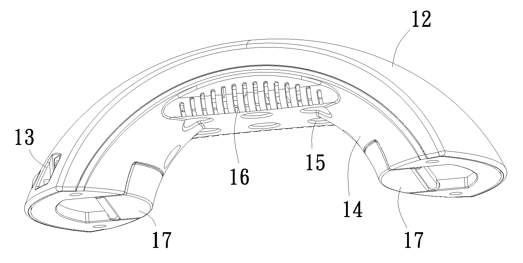
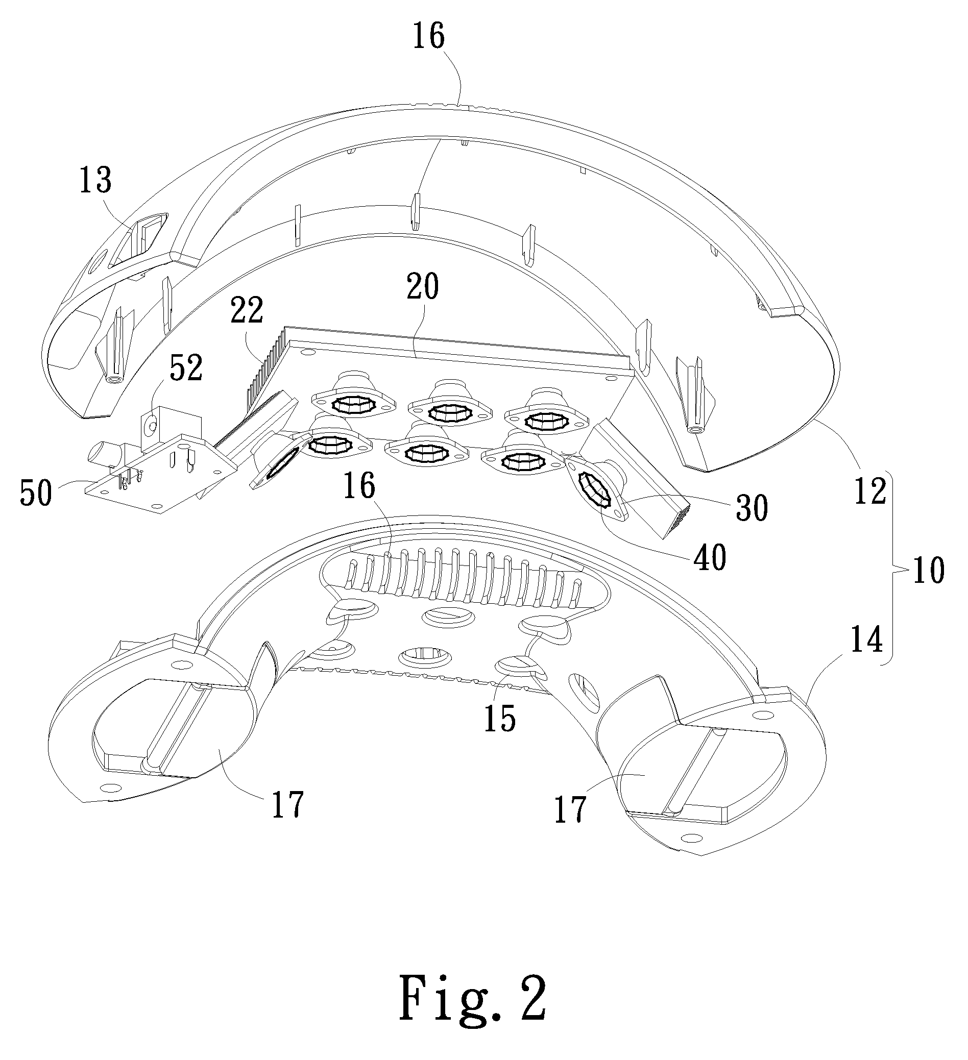
[0013]With reference to FIGS. 2 and 3 for an exploded view and a perspective view of a nail gel solidification apparatus in accordance with a preferred embodiment of the present invention respectively, the nail gel solidification apparatus comprises a housing 10, a control circuit board 20, a plurality of reflecting lamp holders 30, a plurality of LED elements 40 and a power supply module 50.

[0014]The housing 10 is substantially in an arc shape, and includes an upper casing 12 and a lower casing 14, and the upper casing 12 and / or the lower casing 14 includes a plurality of heat dissipating holes 16, and the lower casing 14 includes a plurality of through holes 15 corresponding to the reflecting lamp holders 30 and the LED elements 40.

[0015]The control circuit board 20 is installed in the housi...


PUM


Abstract

The present invention discloses a nail gel solidification apparatus including a housing, a control circuit board, a plurality of reflecting lamp holders, a plurality of light emitting diode (LED) elements and a power supply module. By replacing the traditional lamp with the LED elements of the reflecting lamp holders, the invention provides longer using life and lower power consumption and reduces the solidification time for nail gels.

Description

FIELD OF THE INVENTION[0001]The present invention relates to a nail gel solidification apparatus, in particular to an artificial nail gel solidification apparatus.BACKGROUND OF THE INVENTION[0002]With reference to FIG. 1 for a conventional nail gel (or nail polish) solidification apparatus 1, the nail gel solidification apparatus 1 adopts a lamp 2, particularly an ultraviolet (UV) lamp, as a light source for solidifying the nail gel. However, the illumination of the lamp 2 produces a relatively large quantity of heat and causes a rise of resistance in circuits, and thus the life of a control circuit will be shortened after a long time of use. In the lamp 2 as shown in FIG. 2, the light source is scattered in different directions, not only wasting electric power, but also requiring more time for the solidification of the nail gel. The life of the lamp 2 is also shorter, and it is necessary to replace the lamp 2 more frequently, and thus it incurs a higher cost. Furthermore, the nail ...

Claims


Application Information

Patent Timeline
IPC IPC(8): F26B3/28F26B3/30F26B25/06
CPCA45D29/00
Inventor CHANG, PAO-MIN
Owner CHANG PAO MIN
Features
  • Generate Ideas
  • Intellectual Property
  • Life Sciences
  • Materials
  • Tech Scout
  • Unparalleled Data Quality
  • Higher Quality Content
  • 60% Fewer Hallucinations
Learn More