Concentrated solar thermal energy collection device

a solar thermal energy and collector technology, applied in the field of solar thermal energy collectors, can solve the problems of large size of typical parabolic trough mirrors, high cost of manufacture and transportation of oversized parabolic trough mirrors, and large dimension, so as to improve thermal energy focusing and facilitate manufacturing, transportation and installation.

Inactive Publication Date: 2010-11-25
RENEWABLE ENERGY GROUP
View PDF28 Cites 16 Cited by
  • Summary
  • Abstract
  • Description
  • Claims
  • Application Information

AI Technical Summary

Benefits of technology

[0010]This patent application discloses structure and use of concentrated solar thermal energy collector modules, installed individually, or in an array configuration. Because of the modular design, the individual collector modules are easier to manufacture, transport, and install. Systems of vary

Problems solved by technology

However, the size of a typical parabolic trough mirror may still be quite large.
Manufacture and transport of oversized parabolic trough mirrors is likely to be cost-prohibitive for smaller-scale high-volume use, such as, household use.
However, even the individual mirrors have relativel

Method used


Image

  • Concentrated solar thermal energy collection device
  • Concentrated solar thermal energy collection device
  • Concentrated solar thermal energy collection device

Examples


example circulation

Systems

[0043]Some example systems employing concentrated solar collectors are discussed below.

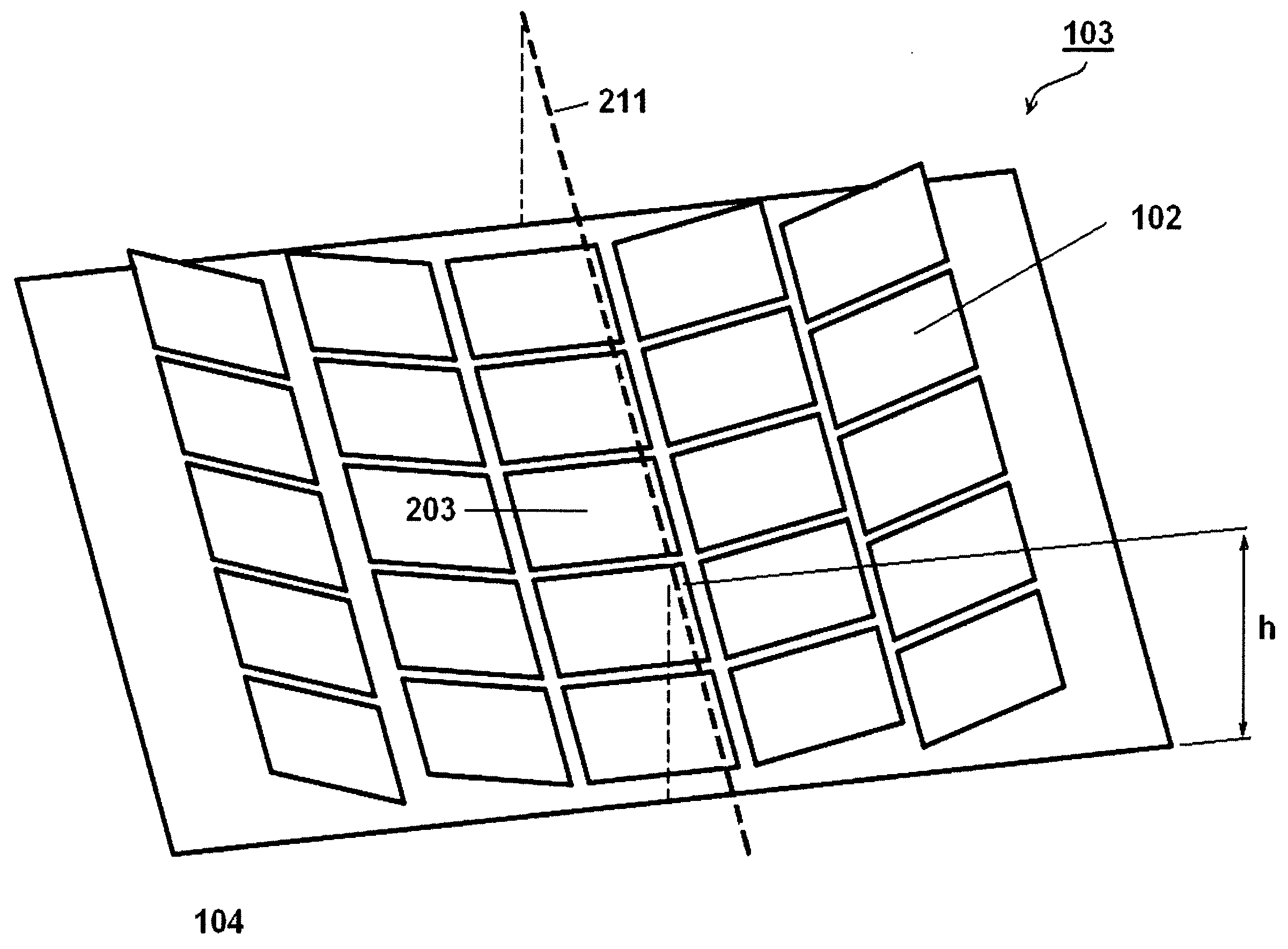
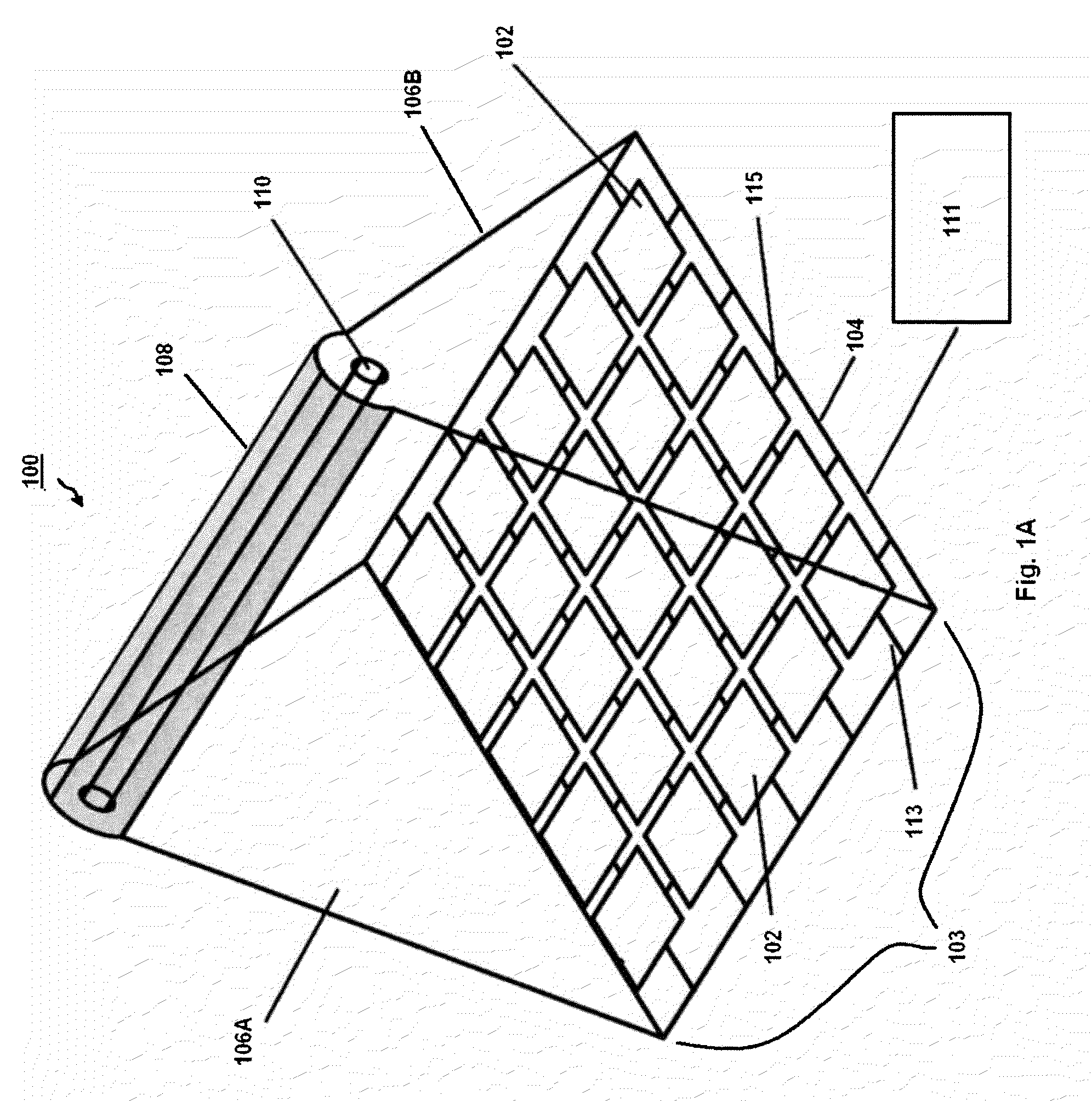
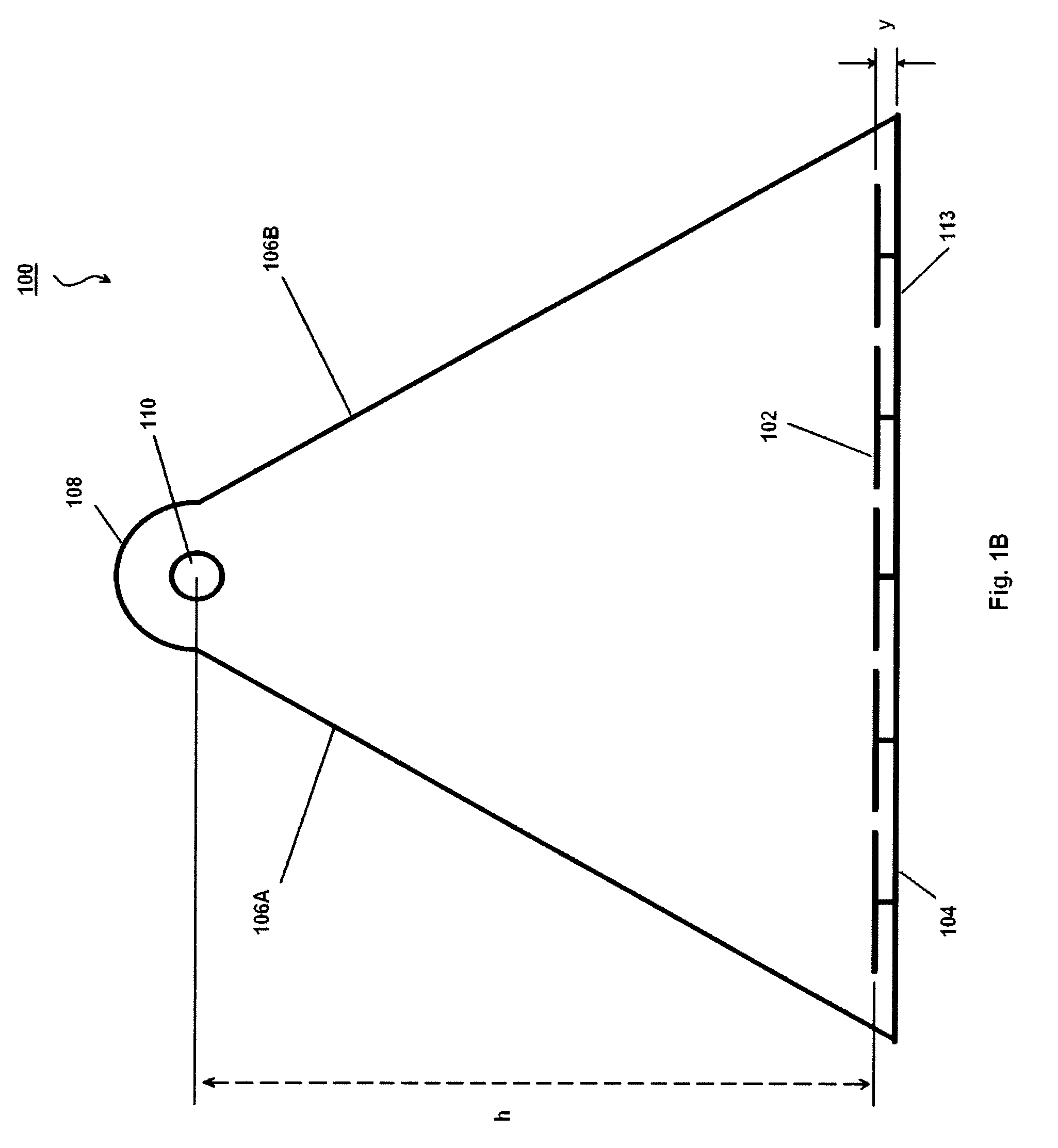
[0044]FIG. 9 shows an example absorption chiller system. As shown in FIG. 9, an absorption chiller system 900 is used to provide a cold fluid for various applications, such as, space cooling, air conditioning, refrigeration, ice-making, cold storage etc. A heat-source fluid (e.g., hot water) is used as a source of heat that evaporates a coolant inside the absorption chiller chamber 965. The coolant may be chilled water or other chilled fluids. The heat-source fluid at a relatively lower temperature goes into the fluid inlet pipe 742 at the inlet port 740, collects concentrated solar thermal energy from the modules 300A-D, and flows into a heat source fluid inlet pipe 960 coupled to the outlet port 750 of the fluid outlet pipe 748. The hot fluid temperature requirement is between 88° C. to 100° C. The concentrated solar collector can achieve these temperature range even at low sun ray.

[0045]...


PUM


Abstract

This patent application discloses structure and use of concentrated solar thermal energy collector modules, installed individually, or in an array configuration. Because of the modular design, the individual collector modules are easier to manufacture, transport, and install. Systems of varying scale and varying thermal output may be built by custom arrangement of individual collector modules. Each module comprises a tiltable mirror array, a support frame for the mirror array, a heat absorption tube at a focal point of the mirror array, a parabolic mirror concentrator above the heat absorption tube, and two transparent protective panels coupled between the mirror concentrator with the support frame. The heat absorption tube may be a sealed heat tube, or a fluid circulation conduit. The mirrors are configured to be positionally adjusted to improve focusing of thermal energy and/or to track the changing position of the sun.

Description

BACKGROUND[0001]1. Field of the Invention[0002]This invention relates generally to solar thermal energy collector, and more specifically, to modular solar collector devices with movable mirrors for concentrating solar energy to heat up a fluid.[0003]2. Related Arts[0004]Solar energy is widely recognized as a valuable environment-friendly renewable energy source. Solar energy is harnessed in various ways. For example, solar optical energy may be converted into electrical energy by using photovoltaic solar cells. Alternatively, solar thermal energy may be used by collecting sunlight as a thermal energy source. The collected solar thermal energy may be used to directly or indirectly heat up a target, or to generate vapor to run a turbine that generates electricity. Conventionally, harnessing solar thermal energy is recognized as a relatively simpler and cheaper technology than using photovoltaic cells.[0005]Parabolic trough mirrors / reflectors have been used to concentrate solar thermal...

Claims


Application Information

Patent Timeline
IPC IPC(8): F24J2/10F24S23/70
CPCY02B10/20F24J2/14F22B1/006F24J2/18Y02E10/45F24J2/16F24S23/74F24S23/77F24S23/79Y02E10/40
Inventor FUNG, TAK PUI JACKSON
Owner RENEWABLE ENERGY GROUP
Why Eureka
Try Eureka