Synchronization circuits and methods usable in shutter glasses
a technology of synchronization circuits and shutter glasses, applied in the field of synchronization circuits and methods usable in shutter glasses, can solve the problems of further reduction of power consumption, and achieve the effect of further reducing power consumption
- Summary
- Abstract
- Description
- Claims
- Application Information
AI Technical Summary
Benefits of technology
Problems solved by technology
Method used
Image

Examples
first embodiment
of the Present Invention
[0057]FIG. 5 illustrates an exemplary configuration of a 3D stereoscopic picture viewing system to which a first embodiment of the present invention has been applied.
[0058]In FIG. 5, the 3D stereoscopic picture viewing system 11 includes a television 21, a transmitting apparatus 22, and shutter glasses 23.
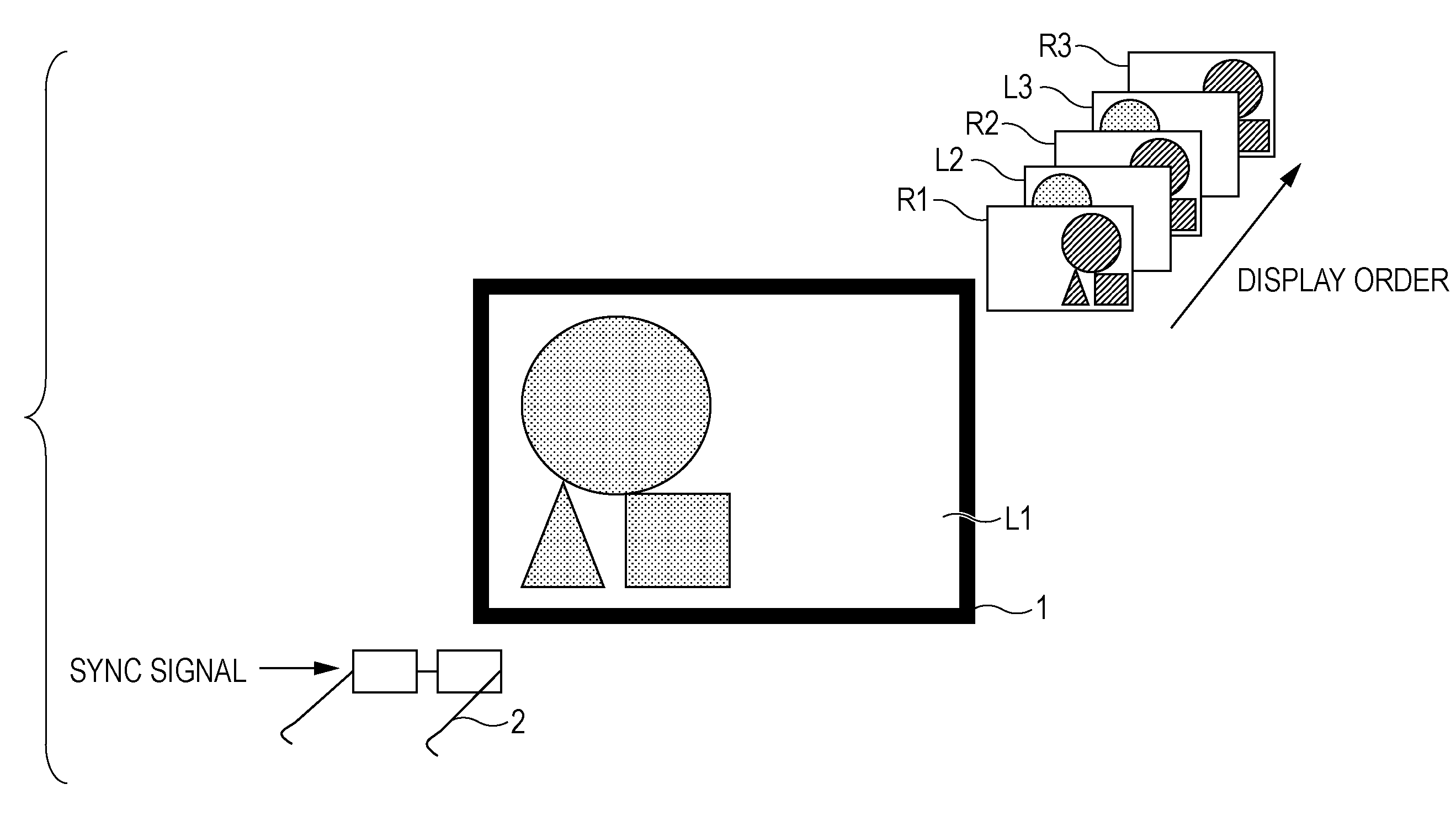
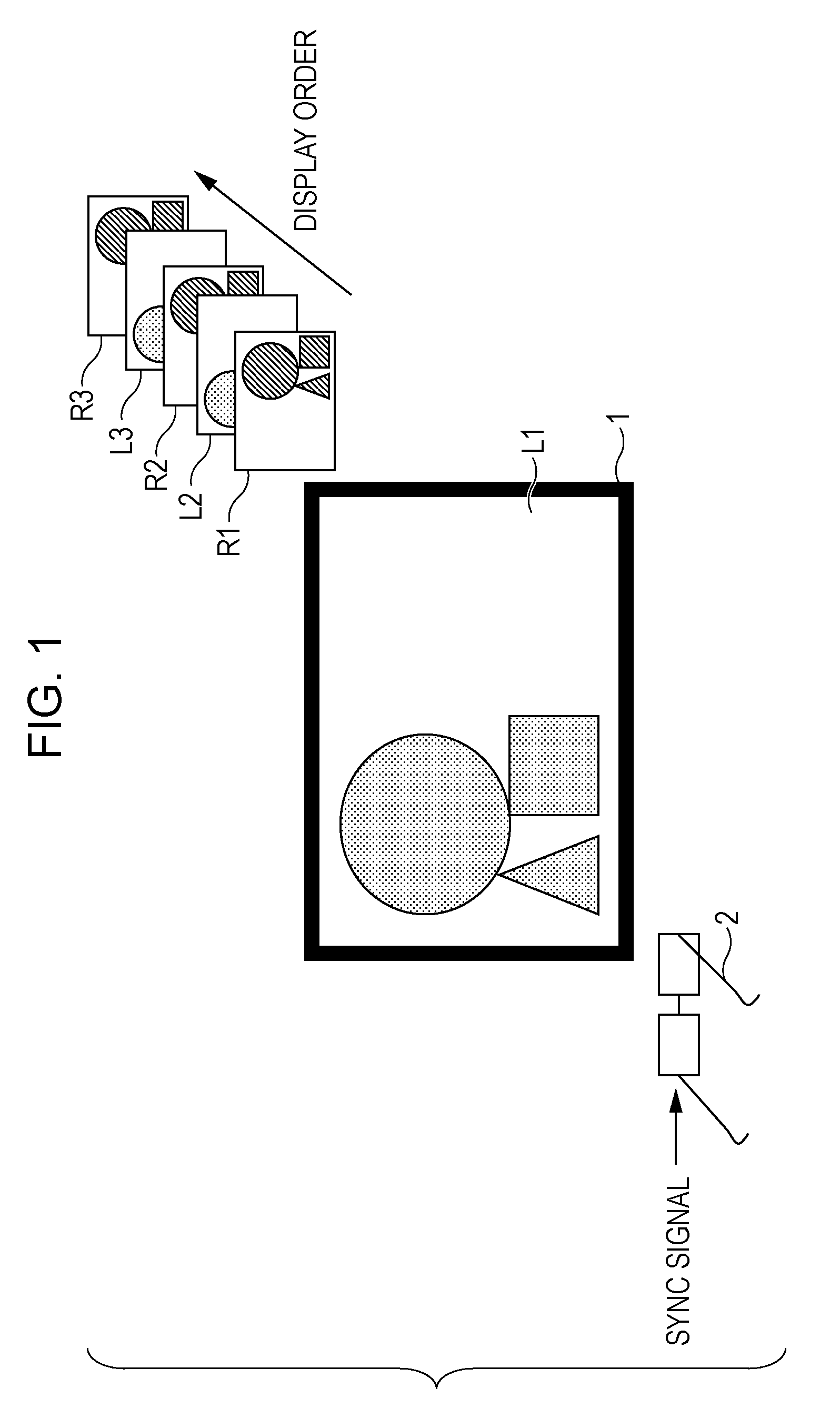
[0059]The television 21 receives externally-provided 3D stereoscopic content data (i.e., 3D stereoscopic picture data), and on the basis of that 3D stereoscopic picture data, displays 2D pictures that cause the user to perceive a 3D stereoscopic picture. More specifically, the television 21 is an LCD, PDP, or similar flat panel display that alternately displays left-eye and right-eye pictures having parallax. It should be appreciated that the format of the 3D stereoscopic picture data received by the television 21 is not particularly limited. The format of the received 3D stereoscopic picture data may be, for example, a format wherein a left-eye picture and ...
second embodiment
of the Present Invention
[0236]FIG. 29 illustrates a 3D stereoscopic picture viewing system to which a second embodiment of the present invention has been applied, and configured such that a sync signal is transmitted in a wired manner for the first 128 periods.
[0237]The 3D stereoscopic picture viewing system 101 in FIG. 29 includes a television 111, shutter glasses 112, and a wired cable 113 that transmits a sync signal.
[0238]The functions of the transmitting apparatus 22 shown in FIG. 5 are built into the television 111. The television 111 sends the first 128 periods of the sync signal to the shutter glasses 112 via the wired cable 113. The shutter glasses 112 receive the first 128 periods of the sync signal via the wired cable 113. Once the first 128 periods of the sync signal have been sent and received, the shutter glasses 112 are disconnected from the wired cable 113. In all other respects, the television 111 is similar to the television 21 shown in FIG. 5, and the shutter glas...
third embodiment
of the Present Invention
[0239]FIG. 30 illustrates a 3D stereoscopic picture viewing system to which a third embodiment of the present invention has been applied.
[0240]The 3D stereoscopic picture viewing system 121 shown in FIG. 30 includes a television 21, a cradle 131, a connecting cable 132, and shutter glasses 133.
[0241]The cradle 131 includes functions similar to those of the transmitting apparatus 22 shown in FIG. 5, and is connected to the television 21 by the connecting cable 132. In addition, the shutter glasses 133 can be placed on top of the cradle 131. When the shutter glasses 133 are placed on top of the cradle 131, contacts 141a and 141b on the cradle 131 make an electrical connection with contacts 141c and 141d on the shutter glasses 133.
[0242]The cradle 131 acquires a sync signal from the television 21 via the connecting cable 132, and sends the sync signal to the shutter glasses 133 placed thereon via the contacts 141a and 141b. Additionally, the cradle 131 includes ...
PUM
 Abstract
Description
Claims
Application Information
 - R&D Engineer
- R&D Manager
- IP Professional
- Industry Leading Data Capabilities
- Powerful AI technology
- Patent DNA Extraction
Browse by: Latest US Patents, China's latest patents, Technical Efficacy Thesaurus, Application Domain, Technology Topic.
© 2024 PatSnap. All rights reserved.Legal|Privacy policy|Modern Slavery Act Transparency Statement|Sitemap