Toner cartridge, image forming apparatus, method of recycling toner cartridge

a technology of toner cartridges and image forming apparatus, which is applied in the field of toner cartridge recycling technology, can solve the problem of limiting the freedom of layou

Active Publication Date: 2010-11-25
RICOH KK
View PDF71 Cites 65 Cited by
  • Summary
  • Abstract
  • Description
  • Claims
  • Application Information

AI Technical Summary

Benefits of technology

[0009]A second object is to provide a toner cartridge that is configured to prevent misalignment of the receptacle holding member due to the rotation of the toner receptacle, and that can be set not only vertically but also horizontally.
[0010]A third object is to provide a toner cartridge that is configured to discharge a stable amount of toner to the image forming apparatus, and that can be set not only vertically but also horizontally so as to allow freedom in the layout.

Problems solved by technology

However, this structure limits the freedom of layout.

Method used


Image

  • Toner cartridge, image forming apparatus, method of recycling toner cartridge
  • Toner cartridge, image forming apparatus, method of recycling toner cartridge
  • Toner cartridge, image forming apparatus, method of recycling toner cartridge

Examples


Embodiment Construction

[0048]Exemplary embodiments of the present invention will be described below with reference to accompanying drawings. The present invention is not limited to these embodiments. An embodiment of an electrophotographic printer (hereinafter, “printer”) is described below as an image forming apparatus to which the present embodiment is applied.

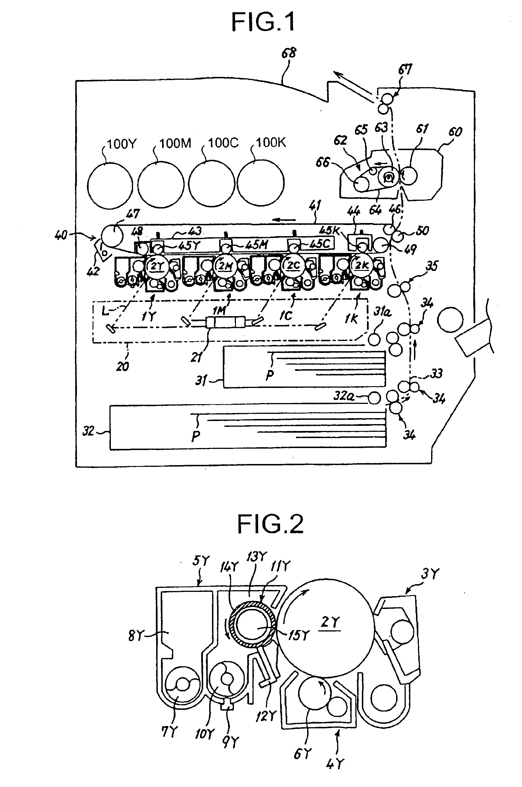
[0049]FIG. 1 is a schematic of an internal structure of the printer. The printer includes four process cartridges 1Y, 1M, 1C, and 1K for creating toner images of yellow, magenta, cyan, and black (hereinafter, “Y, M, C, and K”) colors, respectively. The process cartridges 1Y, 1M, 1C, and 1K use toner of different colors Y, M, C, and K, but have the same structure, and are replaced when they reach their end of life.

[0050]The process cartridge 1Y for creating a Y toner image is taken as an example in FIG. 2. The process cartridge 1Y includes a photosensitive drum 2Y, a drum cleaning unit 3Y, a decharging unit (not shown), a charging unit 4Y, and a de...


PUM


Abstract

An insertion passage 104Y for inserting a suction nozzle 73Y fixed to an image forming apparatus is provided on a holder 102Y, and a connecting passage 114Y that connects the insertion passage 104Y and a toner storage section 106Y of the holder 102Y is provided. After the toner sent from bottle 101Y to the holder 102Y falls towards the connecting passage 104Y, the toner flows into the suction nozzle 73Y through the connecting passage 114Y and is then discharged out of the holder 102Y. An airtightness between the insertion passage 114Y and the suction nozzle 73Y inserted into the insertion passage 114 Y is superior than an airtightness between the bottle 101Y and the holder 102Y engaged with the bottle 101Y.

Description

CROSS-REFERENCE TO RELATED APPLICATIONS[0001]This patent application is a division of and claims the benefit of priority under 35 U.S.C. § 120 from U.S. application Ser. No. 10 / 574,855 filed Mar. 26, 2007 which is the National Stage Entry of PCT / JP05 / 14793 filed Aug. 5, 2005, and claims the benefit of priority under 35 U.S.C. § 119 from Japanese patent application nos. JP 2004-241566, filed on Aug. 20, 2004 and JP 2004-230523, filed on Aug. 6, 2004 in the Japan Patent Office, the entire contents of each of which are incorporated by reference herein.TECHNICAL FIELD[0002]The present invention relates to a technology for recycling toner cartridges of image forming apparatuses.BACKGROUND ART[0003]Image forming apparatuses generally employ an electrophotography method or a direct recording method to form toner images on a recording medium. Copiers, facsimile machines, printers are the examples of an image forming apparatus.[0004]In the electrophotography method, a toner image is formed f...

Claims


Application Information

Patent Timeline
Patent Type & Authority Applications(United States)
IPC IPC(8): G03G15/08
CPCG03G15/0872G03G15/0894G03G15/0879G03G21/10G03G15/08
Inventor KURENUMA, TAKEROHOGATA, FUMIOTERAZAWA, SEIJIYAMANE, MASAYUKITATSUMI, KENZOTSUDA, KIYONORIKITA, EMITAGUCHI, NOBUYUKINARUMI, SATOSHISUDO, KAZUHISA
Owner RICOH KK
Why Eureka
Try Eureka