Exercise Machine for Providing Resistance to Ambulatory Motion of the User

Active Publication Date: 2010-11-25
TURNER JOSEPH
View PDF47 Cites 26 Cited by
  • Summary
  • Abstract
  • Description
  • Claims
  • Application Information

AI Technical Summary

Benefits of technology

[0012]The flywheel assembly positioned opposite the spring assembly across the spool assembly provides both an initial stationary inertia that the user must overcome in order to initiate rotation of the assemblies, and a rotating inertia once the system is in rotational motion. The flywheel acts as a governor to balance the changing forces associated with the spring assembly as the coil spring therein tightens and subsequently loosens. Positioned on the spin axle between the flywheel assembly and the spring assembly is a spool assembly which allows t

Problems solved by technology

Clearly the process of dragging such a weight sled across a floor surface indoors can be problematic.
Even when used outdoors, the typical weight sled offers a very inconsistent resistive force to the user and often results in intervals of high resistance (where the sled sticks or digs into the ground) followed by intervals of very little resistance (where the sled looses conta

Method used


Image

  • Exercise Machine for Providing Resistance to Ambulatory Motion of the User
  • Exercise Machine for Providing Resistance to Ambulatory Motion of the User
  • Exercise Machine for Providing Resistance to Ambulatory Motion of the User

Examples


Embodiment Construction

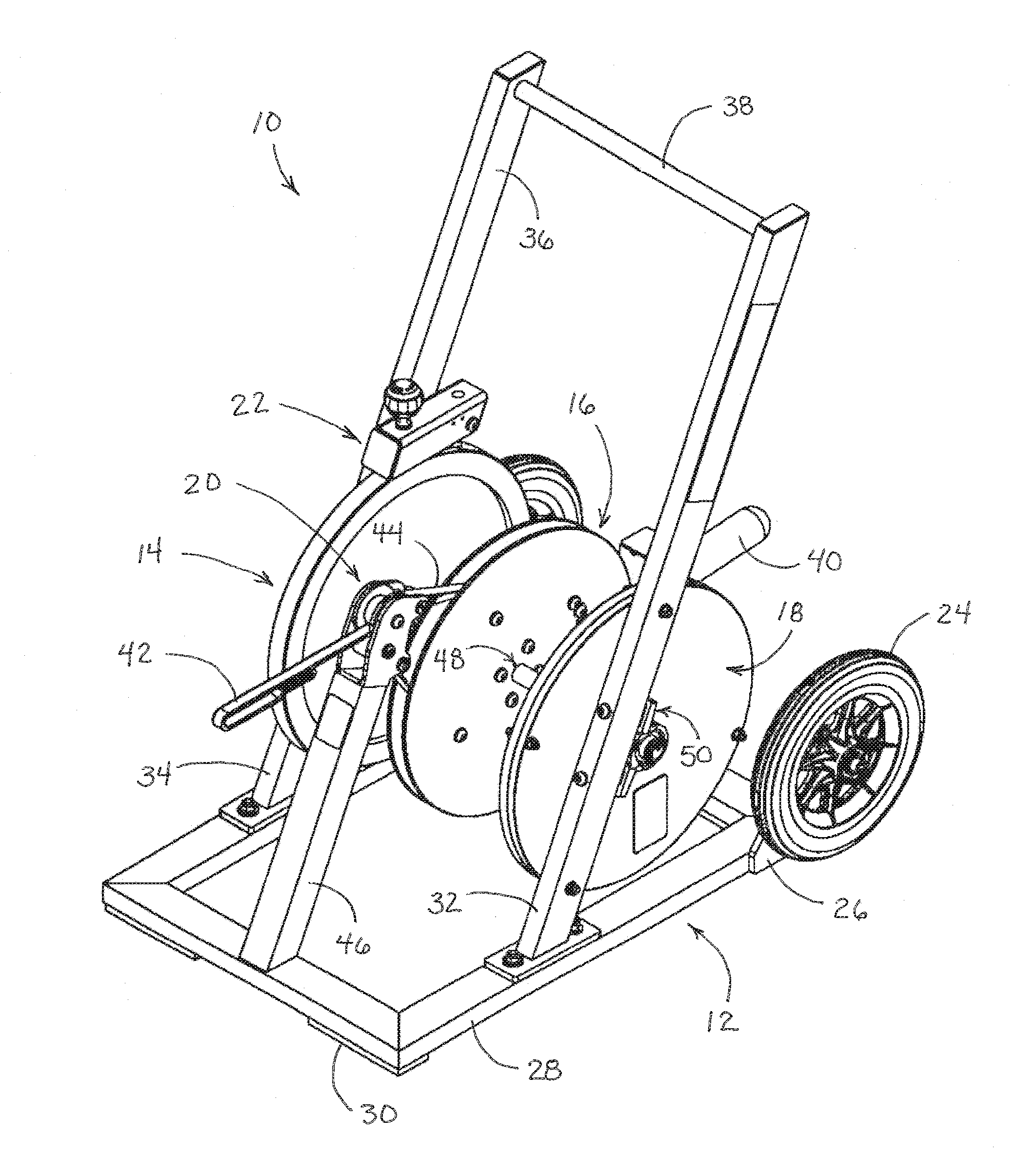
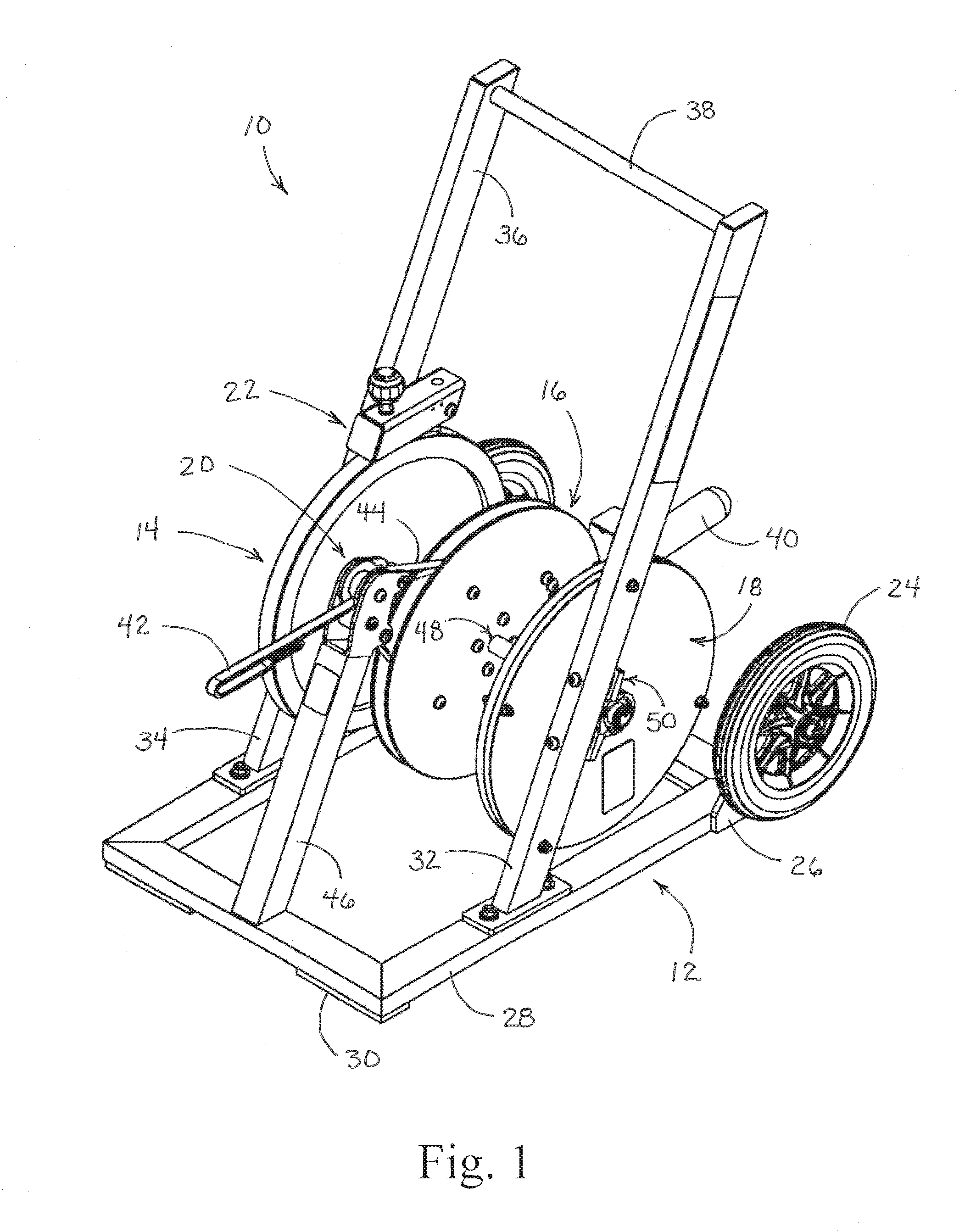
[0021]Reference is made first to FIG. 1 for a description of the overall system of the present invention. As indicated above, the exercise machine system of the present invention is intended to provide a means for exercising by subjecting oneself to a resistive force while stepping, walking, or running away from a fixed point. Exercise machine 10 of the present invention is comprised of a number of individual assemblies. Exercise machine 10 may be seen to comprise frame assembly 12 which incorporates and supports fly wheel assembly 14, spool assembly 16, and spring assembly 18. The manner in which these assemblies interact is described in more detail below.

[0022]A number of additional smaller assemblies are also included in the overall exercise machine system 10 of the present invention. These smaller assemblies, which are mounted at various places on frame assembly 12, include lead guide rollers assembly 20 and resistance adjustment assembly (brake assembly) 22. The structures of t...


PUM


Abstract

An exercise machine that provides a generally consistent resistive force against a user who walks, steps, or runs away from the machine as part of a strength training exercise program. The machine is built upon a movable frame having transport wheel assemblies that allow the exercise machine to be placed on an indoor floor surface or on the ground outdoors. The frame of the device further supports three parallel spinning assemblies that together allow a length of linear strap attached to the user to run out from the machine and thereafter be retracted or rewound back into the machine. The spinning assemblies include a flywheel assembly, a spool assembly, and a spring assembly, each co-axially arranged on a spin axle extending across the frame. The spring assembly is fixed against the frame and incorporates a coil spring that tightens with the rotation of the spin axle in a first direction (allowing the linear run-out strap to extend out from the spool assembly). The coil spring in the spring assembly thereafter tends to direct the rewinding of the strap back onto the spool assembly. The coaxial flywheel assembly provides both an initial stationary inertia and a subsequent rotational inertia. The flywheel acts as a governor to balance the changing forces associated with the resistive force increasing in the spring assembly. Positioned on the spin axle between the flywheel assembly and the spring assembly is a spool assembly that allows the strap to unwind and subsequently to be wound back onto the spool. A guide strap may be provided around the spool to maintain the linear run-out strap within the spool assembly. A resistance adjustment assembly presses a brake pad against the perimeter surface of the flywheel to adjust the force required to direct rotation of the system. A weight horn bracket is provided to add additional disc weights if necessary.

Description

CROSS REFERENCES TO RELATED APPLICATIONS[0001]This application claims the benefit under Title 35 United States Code §119(e) of U.S. Provisional Application 61 / 214,078 filed Apr. 20, 2009 the full disclosure of which is incorporated herein by reference.BACKGROUND OF THE INVENTION[0002]1. Field of the Invention[0003]The present invention relates generally to exercise machines and systems for providing resistive force exercise to the user. The present invention relates more specifically to an exercise machine structured to provide a consistent force resisting the ambulatory (walking and / or running) motion of a user moving away from and then back towards the machine.[0004]2. Description of the Related Art[0005]Many exercise regimens call for the repeated movement of the exercising individual from a first point to a second point, typically across a gym floor or across an outdoor field. In some cases this movement is simply a straight line run from one point to the next. In some cases the...

Claims


Application Information

Patent Timeline
IPC IPC(8): A63B21/06A63B21/045
CPCA63B2071/025A63B2208/0204A63B21/00069A63B21/015A63B21/0618A63B71/02A63B21/153A63B21/225A63B23/0405A63B23/047A63B21/1415A63B21/4007
Inventor TURNER, JOSEPH
Owner TURNER JOSEPH
Why Eureka
Try Eureka