
Guidable cutting instrument

a cutting instrument and guide technology, applied in medical science, surgery, vaccination/ovulation diagnostics, etc., can solve the problems of limited use of prior art assembly, limited needle negotiation ability, and limited ability of needle to avoid body structures and organs situated in the path of needl

Active Publication Date: 2010-11-25
COOK MEDICAL TECH LLC
View PDF27 Cites 45 Cited by
  • Summary
  • Abstract
  • Description
  • Claims
  • Application Information

AI Technical Summary

Benefits of technology

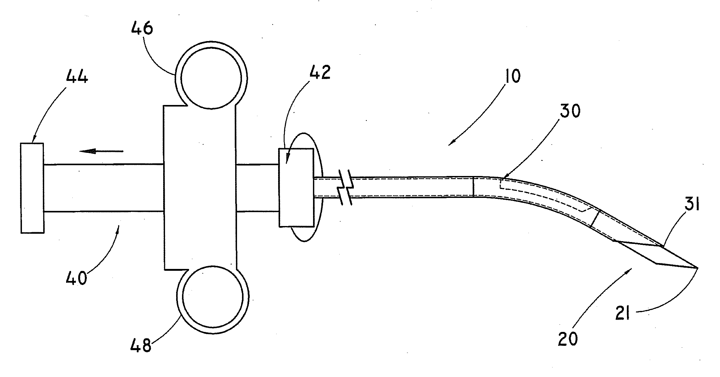
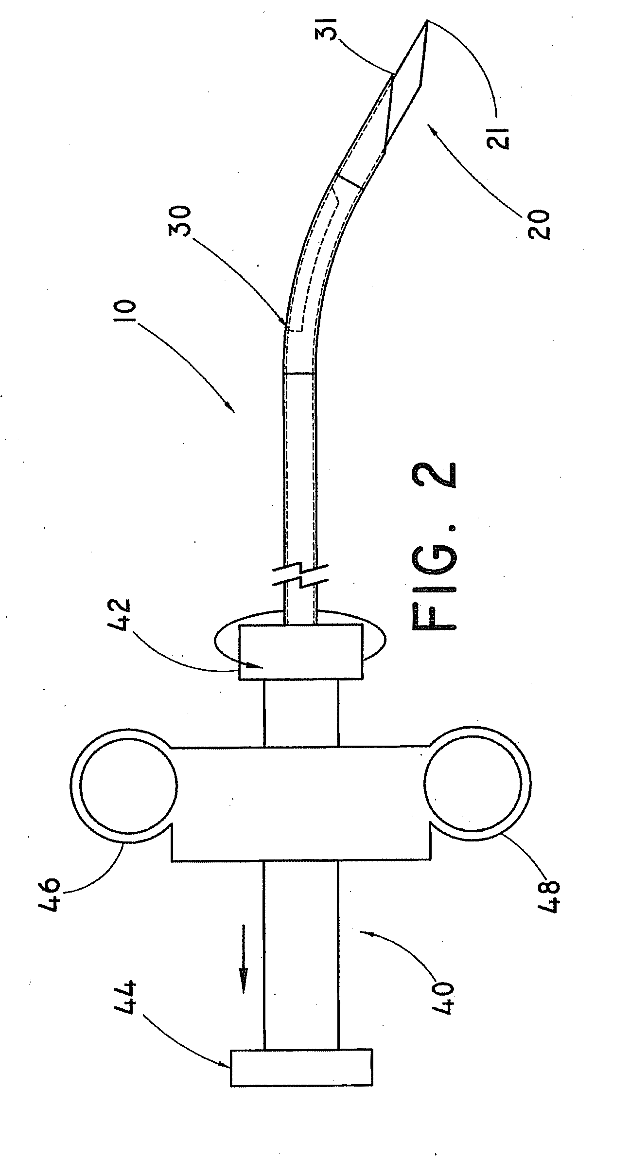
The present invention provides a cutting instrument for use in retrieving tissue specimens from a tissue mass. The instrument includes a cannula and a stylet, which can be extended and rotated relative to each other to define a curved condition or a linear condition. The cannula has a distal portion with a curve, and the stylet has a distal portion with a specimen-receiving notch and a curve. The instrument is designed to be navigated through the body of a patient to approach the tissue mass and capture the specimen. The technical effect of the invention is to provide a precise and efficient tool for retrieving tissue specimens from a tissue mass.

Problems solved by technology

However, the ability of the needle to negotiate through curves in the vasculature, and particularly, the ability of the needle to avoid body structures and organs situated in the path of the needle, is limited.
As a result, use of the prior art assembly is generally limited to a “straight shot” type of procedure, in which the needle is inserted percutaneously and directly advanced in generally linear fashion to a target lesion that is accessible without significant obstruction.
However, “straight shot” type devices are in large part incapable of being steered, navigated, or otherwise bended around a body organ or other obstruction that may be encountered within the body of the patient.

Method used


Image

  • Guidable cutting instrument
  • Guidable cutting instrument
  • Guidable cutting instrument

Examples


Embodiment Construction

[0017]For purposes of promoting an understanding of the present invention, reference will now be made to the embodiments illustrated in the drawings, and specific language will be used to describe the same. It should nevertheless be understood that no limitation of the scope of the invention is thereby intended, such alterations and further modifications in the illustrated device, and such further applications of the principles of the invention as illustrated therein being contemplated as would normally occur to one skilled in the art to which the invention relates.

[0018]In the following discussion, the terms “proximal” and “distal” will be used to describe the opposing axial portions of the inventive cutting instrument, as well as the axial portions of various component features. The term “proximal” is used in its conventional sense to refer to the portion of the cutting instrument (or component thereof) that is closest to the operator during use of the cutting instrument. The term...


PUM


Abstract

A guidable cutting instrument for cutting a tissue specimen from a tissue mass comprises a cannula having a curve formed along a distal portion thereof, and a stylet having a specimen-receiving notch and a curve formed along a distal portion thereof. The stylet is received in the cannula, and is axially extendable therefrom such that the notch is capable of penetrating the tissue mass. The cannula is axially movable over the extended stylet for severing the specimen from the mass for capture in the notch. The cannula and stylet are each structured and arranged for relative rotation between a first position wherein the cannula curve and the stylet curve are in phase to define a curved condition for a length of the cutting instrument, and a second position wherein the cannula curve or stylet curve is rotated relative to the other curve in a manner to define a generally linear condition of the cutting instrument. The selective relative curvature allows the cutting instrument to be steered around obstructions encountered in the body under real time visualization.

Description

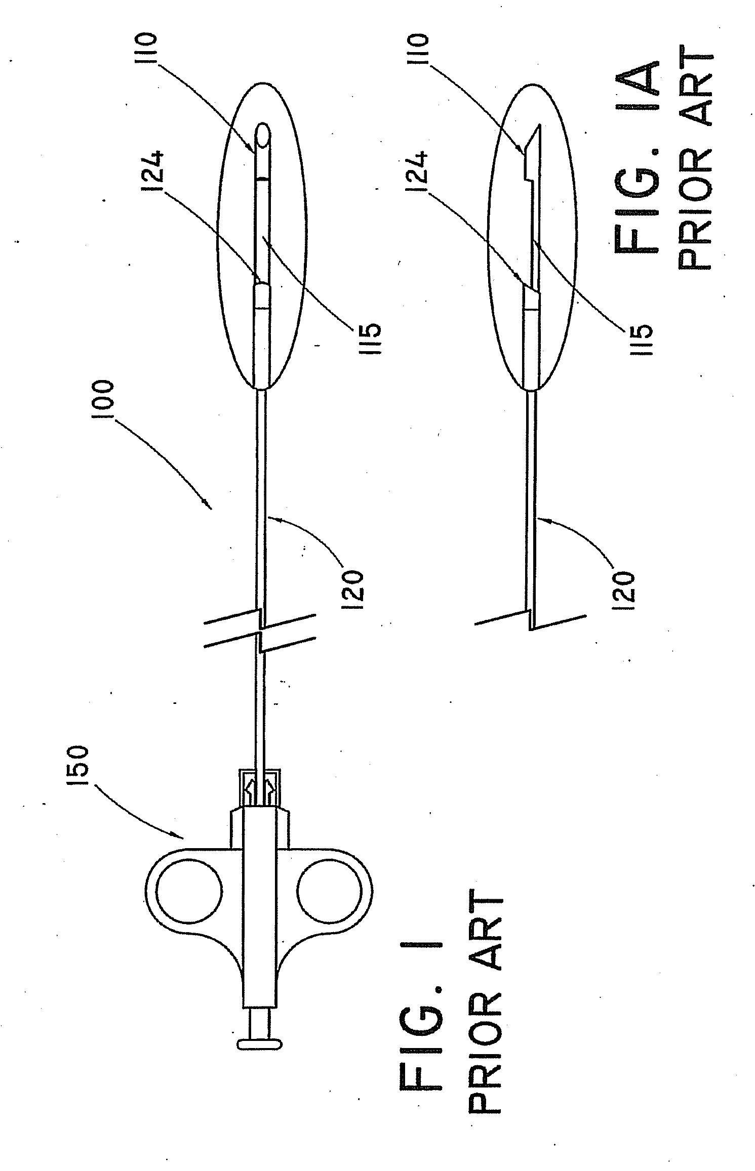
BACKGROUND OF THE INVENTION[0001]1. Technical Field. The present invention relates to a guidable cutting instrument, and more particularly, to a guidable needle for use in biopsy sampling of tissue.[0002]2. Background Information[0003]Biopsy is the removal and study of body tissue for medical diagnosis. Typically, physicians obtain biopsy samples in order to detect tissue abnormalities, such as the presence of a cancerous growth, and / or to determine the extent to which the cancerous growth may have spread in the affected tissue. Various known biopsy instruments may be used to acquire tissue samples from different areas of interest in the body of a patient.[0004]Biopsy instruments often comprise a two-part needle assembly comprising a stylet and cannula. One example of a conventional biopsy instrument is the QUICK-CORE® Biopsy Needle, available from Cook Incorporated, of Bloomington, Ind. The QUICK-CORE® needle 100 is shown in FIGS. 1-1A. Needle 100 includes a stylet 110 and an outer...

Claims


Application Information

Patent Timeline
Patent Type & Authority Applications(United States)
IPC IPC(8): A61B10/02
CPCA61B10/0275
Inventor KOEHLER, CLEVE
Owner COOK MEDICAL TECH LLC
Learn More