Three dimensional shape measurement apparatus, three dimensional shape measurement method, and computer program

a three-dimensional shape and measurement method technology, applied in the direction of mechanical measuring arrangements, instruments, using mechanical means, etc., can solve the problems of difficult to achieve phase unwrapping, method is not suitable for real-time measurement, and requires phase unwrapping

Active Publication Date: 2010-11-25
CANON KK
View PDF11 Cites 63 Cited by
  • Summary
  • Abstract
  • Description
  • Claims
  • Application Information

AI Technical Summary

Benefits of technology

[0007]As described above, a 3D shape measurement technology which can measure an object having an abrupt shape change and discontinuous objects up to a detailed shape using a small number of p...

Problems solved by technology

However, with this method, since phase variations that can be measured are limited to those within a specific area, when a shape change outside the area takes place, phases are aliased, thus requiring phase unwrapping.
However, it becomes difficul...

Method used


Image

  • Three dimensional shape measurement apparatus, three dimensional shape measurement method, and computer program
  • Three dimensional shape measurement apparatus, three dimensional shape measurement method, and computer program
  • Three dimensional shape measurement apparatus, three dimensional shape measurement method, and computer program

Examples


first embodiment

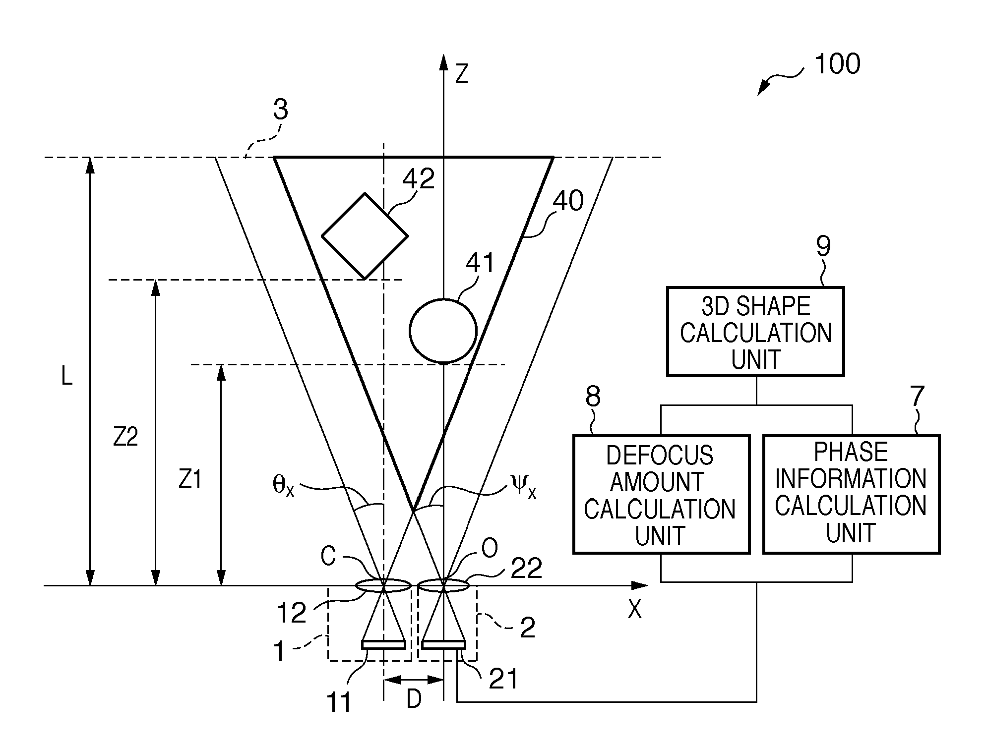
[0032]FIG. 1 is a schematic plan view of a shape measurement apparatus 100 according to the first embodiment of the present invention. An optical center O of a capturing unit 2 is laid out to be an origin of a world coordinate system (X, Y, Z). A Z-axis agrees with the optical axis of the capturing unit 2 to specify an X-axis in a horizontal rightward direction, and a Y-axis in a vertical downward direction. In the first embodiment, the optical axes of a pattern projection unit 1 and the capturing unit 2 are laid out to be parallel to each other. An optical center C of the pattern projection unit 1 is laid out at a position separated by a distance D on the X-axis from the optical center O of the capturing unit 2. A horizontal half field angle of the pattern projection unit 1 is represented by θx, and a vertical half field angle is represented by θy. Also, a horizontal half field angle of the capturing unit 2 is represented by Ψx, and a vertical half field angle is represented by Ψy....

second embodiment

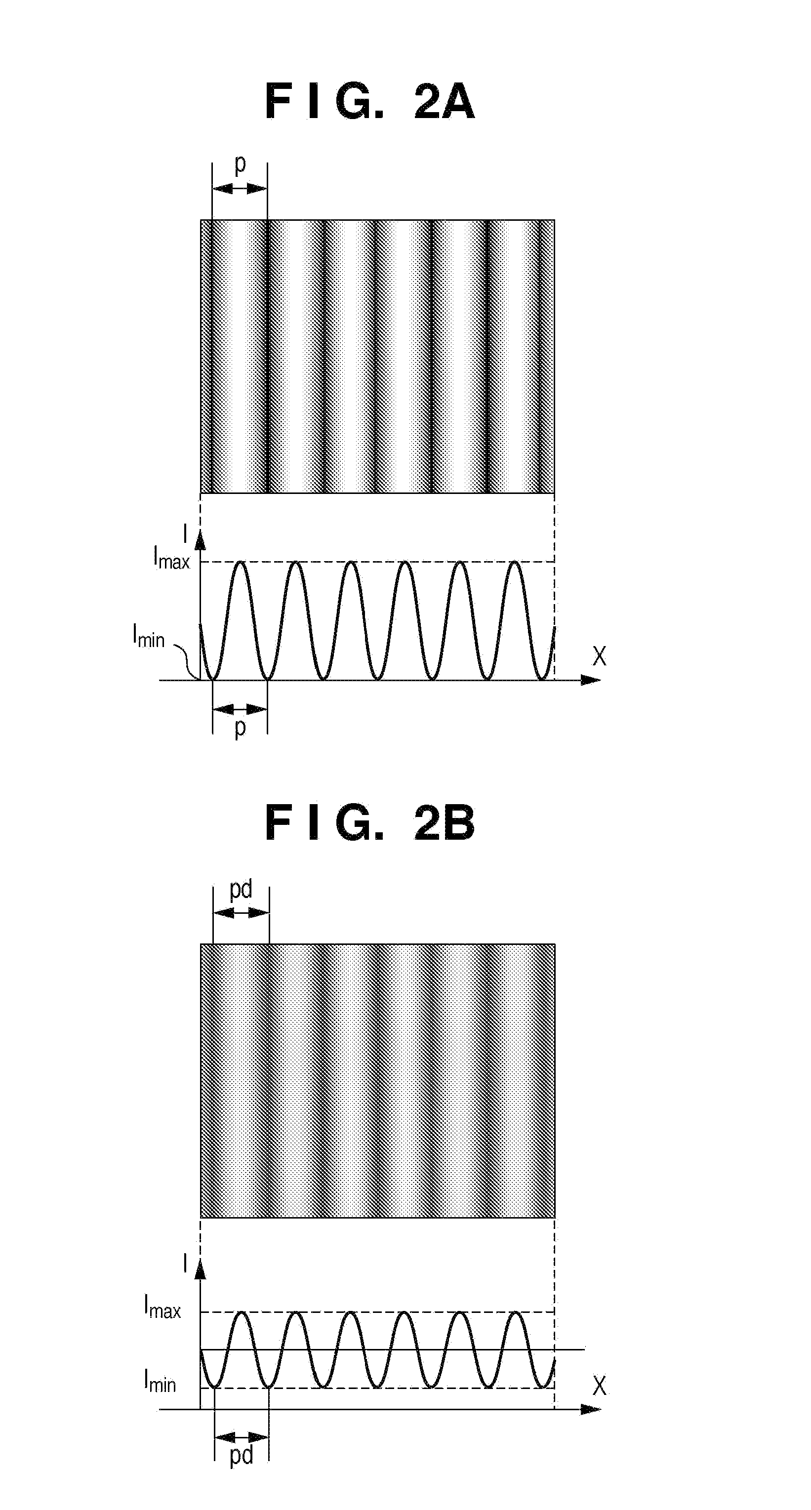
[0086]FIG. 18 is a schematic view of a shape measurement apparatus 200 according to the second embodiment of the present invention. In the arrangement shown in FIG. 18, a projection pattern switching unit 14 is added to that of the first embodiment shown in FIG. 1. The second embodiment uses a phase shift method to acquire phase information. In the phase shift method, three or more different patterns are required to be projected while shifting the phase of a sinusoidal pattern shown in FIG. 2A. In the second embodiment, four different patterns are projected while shifting the phase of the sinusoidal pattern by π / 2.

[0087]Examples of these four different patterns are as shown in FIGS. 19A to 19D. FIGS. 19A to 19D respectively show cases of the phase shift amounts=0, π / 2, π, and 3π / 2. By projecting these four different patterns having different phases, an effect of allowing acquisition of phase information insusceptible to a texture of an object can be obtained. Furthermore, a defocus ...


PUM


Abstract

A 3D shape measurement apparatus for measuring a 3D shape of an object existing on a measurement area, comprising, a pattern projection unit for projecting a pattern having a periodicity onto the measurement area, and a capturing unit for capturing an image of the area where the pattern is projected, wherein the measurement area is specified by a reference plane, a projection area of the pattern projection unit, and a capturing area of the capturing unit, and the pattern projection unit projects the pattern to be focused on the reference plane. The apparatus further comprises a first calculation unit for calculating phase information of a pattern of the captured image, a second calculation unit for calculating defocus amounts of the pattern in the captured image, and a third calculation unit for calculating a 3D shape of the object based on the phase information and the defocus amounts.

Description

BACKGROUND OF THE INVENTION[0001]1. Field of the Invention[0002]The present invention relates to a three dimensional shape measurement apparatus, three dimensional shape measurement method, and computer program.[0003]2. Description of the Related Art[0004]Various three dimensional (3D) shape measurement methods have been proposed. Upon roughly classifying these methods, they include a passive type, which performs a shape measurement using only a capturing device without using any illumination device, and an active type, which uses an illumination device and capturing device in combination. The active type assures higher robustness against an object than the passive type, and can attain a high-precision distance measurement. Even when surface texture information of an object is small, the active type is hardly influenced by the surface texture information since it attains a shape measurement based on a projected illumination pattern. Typical examples of the active type include a meth...

Claims


Application Information

Patent Timeline
IPC IPC(8): G01B11/25G06F15/00
CPCG06T7/0057G01B11/25G06T7/521
Inventor YOSHIKAWA, HIROSHI
Owner CANON KK
Why Eureka
Try Eureka