Method and a system for controlling a lighting system

a lighting system and control method technology, applied in the field of lighting system control, can solve the problems of cumbersome manual commissioning done by a worker who connects the cables of the lighting arrangement to the switch, the control of hundreds of lighting arrangements to generate even the simplest light distribution will become non trivial, and the effect of facilitating subsequent light effect settings

Active Publication Date: 2010-12-02
SIGNIFY HLDG BV
View PDF10 Cites 64 Cited by
  • Summary
  • Abstract
  • Description
  • Claims
  • Application Information

AI Technical Summary

Benefits of technology

[0007]It is an object of the present invention to provide a location commissioning method (and an associated setting method) of a lighting system, which comprises several lighting arrangements, that provides a location commissioning which facilitates subsequent light effect settings.

Problems solved by technology

As one can imagine, the control of hundreds of lighting arrangements to generate even the simplest light distribution will become a non trivial issue.
In an initial phase standard commissioning, i.e. assigning the relationship between each lighting arrangement and a control unit, in an environment with hundreds of lighting arrangements may become cumbersome.
Manual commissioning done by a worker who connects cables from the lighting arrangements to a switch is no longer an option.

Method used


Image

  • Method and a system for controlling a lighting system
  • Method and a system for controlling a lighting system
  • Method and a system for controlling a lighting system

Examples


Embodiment Construction

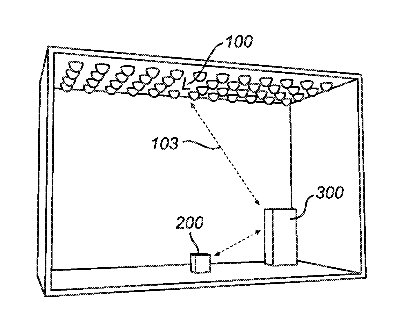
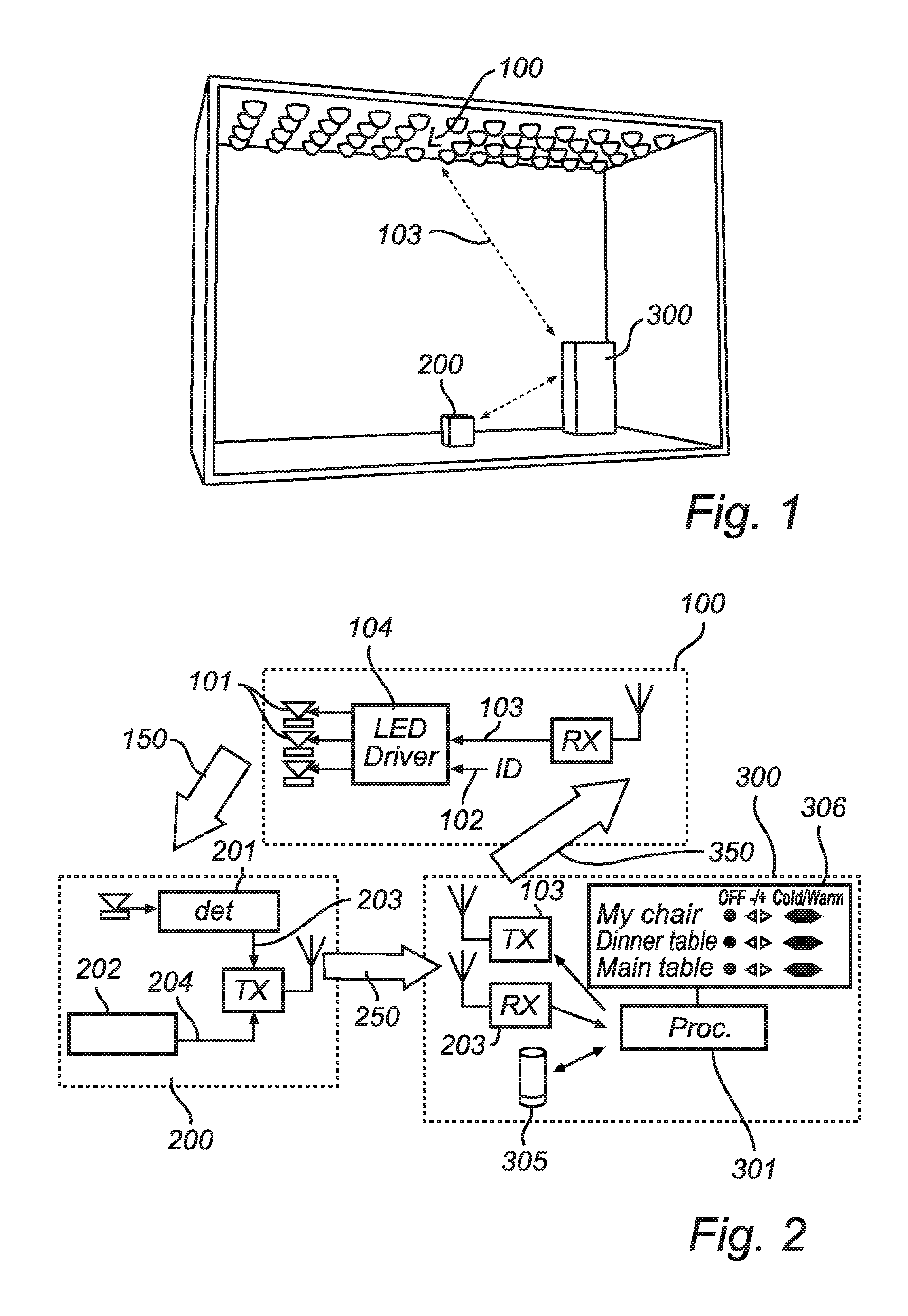
[0097]FIG. 1 shows a schematic drawing of an embodiment of a lighting system according to the present invention. The system consists of three main parts, namely lighting arrangements 100, a user control unit 200, and a main control device 300. The lighting arrangements 100 are for instance mounted in the ceiling of a room. They could for example also be mounted on the walls of the room or in furniture or appliances present in the room. The main control device 300 is arranged to control the lighting arrangements 100, and to receive data 203 from the user control unit 200. Furthermore the main control device 300 is arranged to store and process data. The communication between the main parts of the system is preferably based on wireless communication, but can be based on wired communication as well. The lighting system is useful for location commissioning purposes and produces relevant data for subsequent light control, i.e. light effect settings, enabling different light effects in th...


PUM


Abstract

The present invention relates to a location commissioning method for a lighting system, which comprises several lighting arrangements. Thus, an illuminated position, of for example a room, is selected for the performing the commissioning, which is then associated with that position. This commissioning is called Luxissioning™. The position is assigned a position id, and the light at the position is measured. Light data associated with each one of the lighting arrangements is derived from the measured light, and the light data is associated with the position id. Light transfer data is determined on basis of the light data and current drive data for the lighting arrangements and stored in a light effect setting array for the position id. A light effect setting method is also present, where there is requested a selected light effect at a selected position. For each such request data comprising a position id and a target light effect setting associated with the position is received. The associated initial light effect setting array is derived, for example by retrieving a stored one. Required drive data for the relevant light arrangements, for obtaining the target light effect setting, is determined by means of the light transfer data held in the array, and adjustments are made accordingly, if necessary. Devices and systems for performing the above methods are also addressed by this invention.

Description

FIELD OF THE INVENTION[0001]The present invention relates to a method and a system for controlling a lighting system, which comprises several lighting arrangements, and more particularly to a location commissioning method and an associated setting method according to the preambles of claims 1 and 17 respectively, and to corresponding systems according to the preambles of claims43 and 48.BACKGROUND OF THE INVENTION[0002]The role of electronic control in illumination applications is rapidly growing. The number of lighting arrangements in an environment is increasing, especially with the introduction of SSL (Solid State Lighting) LED lighting, and can involve hundreds of lighting arrangements in the same room. This opens up the possibility for creative light settings, but also the demand for user friendly ways of designing and controlling these complex light effects. As one can imagine, the control of hundreds of lighting arrangements to generate even the simplest light distribution wi...

Claims


Application Information

Patent Timeline
Patent Type & Authority Applications(United States)
IPC IPC(8): H05B37/02
CPCH05B37/029H05B37/0272H05B47/155H05B47/19
Inventor FERI, LORENZOSEKULOVSKI, DRAGANCOLAK, SEL BRIANLINNARTZ, JOHAN PAUL MARIE GERARDDAMINK, PAULUS HENRICUS ANTONIUSGUAJARDO MERCHAN, JORGE
Owner SIGNIFY HLDG BV
Why Eureka
Try Eureka