

Image Audio Processing Apparatus And Image Sensing Apparatus
a technology of image audio processing and image sensing, which is applied in the direction of instruments, television systems, static indicating devices, etc., can solve the problems of difficult control method setting or adjustment of directivity for obtaining an intended audio signal, complex operation of the same, and inability to display the sound level of a sound generated by an obj
- Summary
- Abstract
- Description
- Claims
- Application Information
AI Technical Summary
Benefits of technology
Problems solved by technology
Method used
Image

Examples
example 1
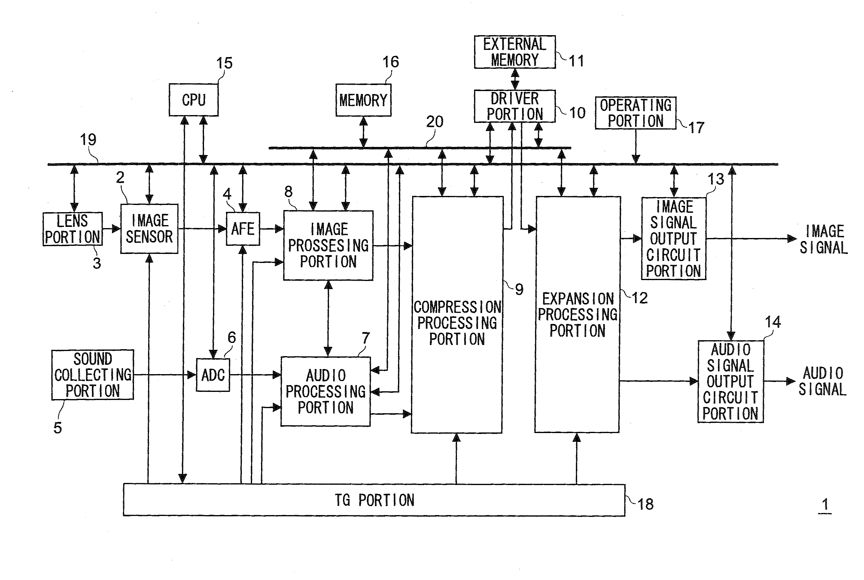
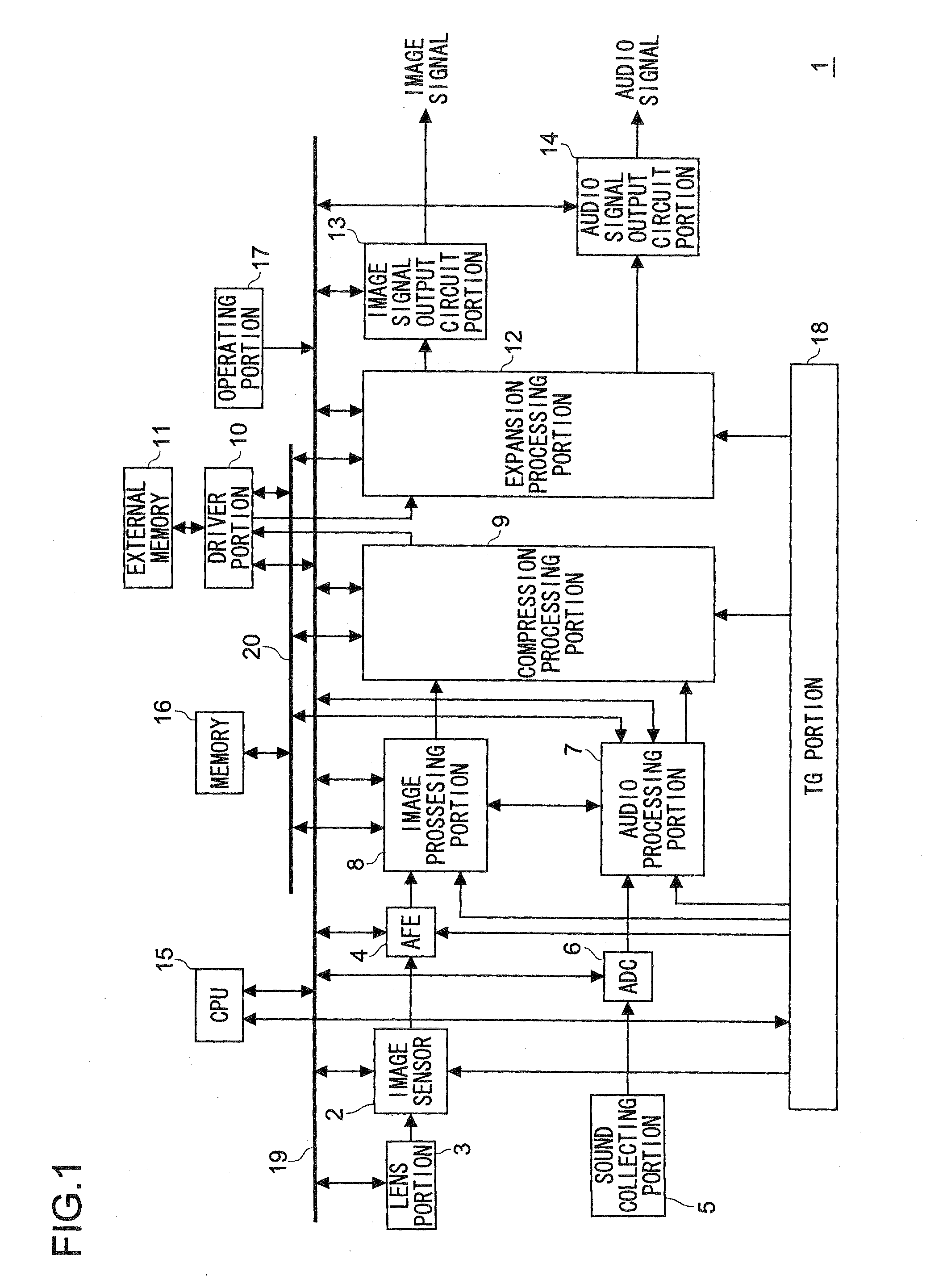
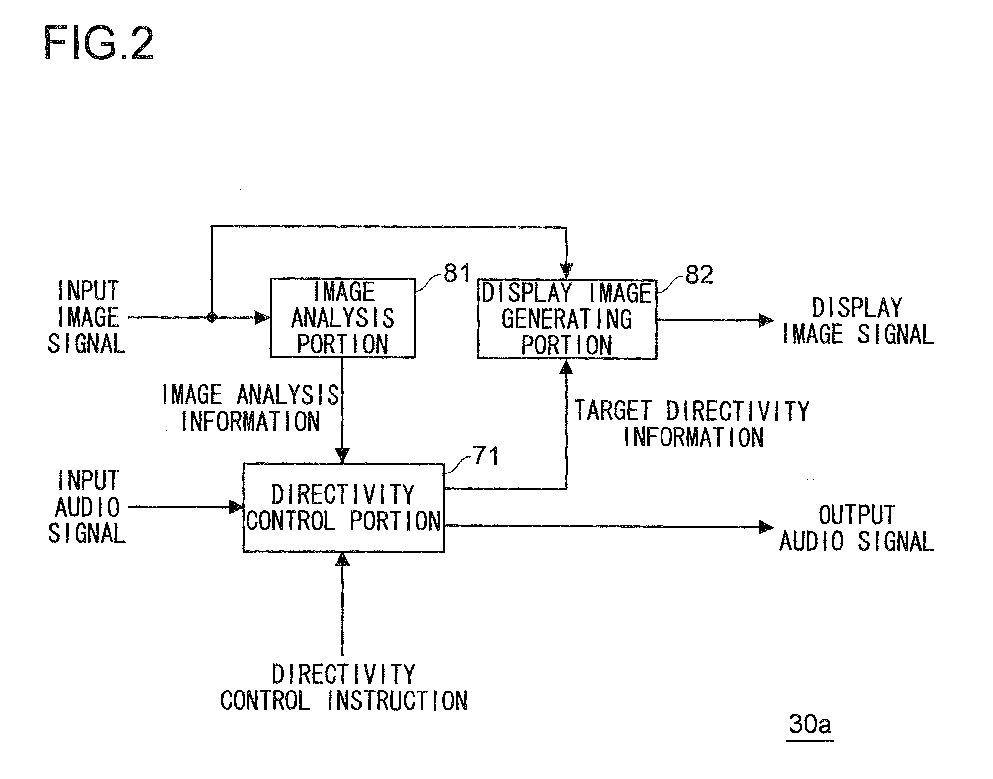
[0057]Example 1 of the image audio processing portion will be described with reference to the drawings. FIG. 2 is a block diagram illustrating a structure of the image audio processing portion of Example 1. As illustrated in FIG. 2, an image audio processing portion 30a includes an image analysis portion 81 for analyzing the input image illustrated in input image signal so as to generate image analysis information, a directivity control portion 71 which controls the directivity of the input audio signal based on the image analysis information generated by the image analysis portion 81 so as to generate the output audio signal and sets the directivity after controlling the input audio signal (i.e., the directivity of the output audio signal, which is referred to as a target directivity hereinafter) so as to generate target directivity information, and a display image generating portion 82 for generating the display image signal to be display image in which an image based on the targe...
example 2
[0092]Example 2 of the image audio processing portion will be described with reference to the drawings. FIG. 7 is a block diagram illustrating a structure of the image audio processing portion of Example 2 and is corresponds to FIG. 2 illustrating the structure of Example 1. Note that in FIG. 7 a part having the same structure as in FIG. 2 is denoted by the same reference symbol, and a detailed description thereof is omitted.
[0093]As illustrated in FIG. 7, an image audio processing portion 30b includes the image analysis portion 81, the directivity control portion 71, and a display image generating portion 82b for generating a display image by superimposing on the input image an image based on image analysis information output from the image analysis portion 81 and target directivity information output from the directivity control portion 71, so as to output the display image signal.
[0094]The display image generating portion 82b of this example is different from Example 1 in that no...
example 3
[0099]Example 3 of the image audio processing portion will be described with reference to the drawings. FIG. 9 is a block diagram illustrating the structure of the image audio processing portion of Example 3 and corresponds to FIG. 2 illustrating the structure of Example 1. Note that in FIG. 9 a part having the same structure as in FIG. 2 is denoted by the same reference symbol, and a detailed description thereof is omitted.
[0100]As illustrated in FIG. 9, an image audio processing portion 30c includes the image analysis portion 81, a directivity control portion 71c for sound level detection which controls the directivity of the input audio signal based on the image analysis information and the directivity control instruction so as to generate the output audio signal for sound level detection, a sound level detection portion 72 for detecting a sound level of the output audio signal for sound level detection output from the directivity control portion 71c for sound level detection so ...
PUM
 Abstract
Description
Claims
Application Information