Car lighting unit for generating a beam of light and a holographic 3D image

a technology for lighting units and cars, applied in fixed installations, lighting and heating apparatuses, instruments, etc., can solve the problems of inability to generate holographic images when the lamp is not switched, and not suitable for generating beams of ligh

Inactive Publication Date: 2010-12-02
KONINKLIJKE PHILIPS ELECTRONICS NV
View PDF9 Cites 37 Cited by
  • Summary
  • Abstract
  • Description
  • Claims
  • Application Information

AI Technical Summary

Benefits of technology

[0018]In a preferred embodiment, the car lighting unit according to the invention is constructed to generate the source-related holographic 3D image within a distance in the range of about 0 to 5 m from the reflector opening. The distance is preferably in the range of about 0 to 2 m, more preferably in the range of about 0 to 0.5 m, more preferably in the range of about 0 to 0.1 m. In this way, the source-related holographic 3D image is substantially not blended by the beam of light from the lighting unit and is visible for an observer, such as another road user. Furthermore, in this way, other users of the road will see both the lighting unit (i.e. especially its signal) and the holographic image at the same time and substantially at the same position.

Problems solved by technology

These prior-art lamps have one or more drawbacks in that they are not suitable for generating a beam of light in accordance with the prescribed specifications, which beam is used for illumination or signaling (i.e. light signaling function), while simultaneously also for generating a holographic 3D image, which can be used, for instance, to provide information.
Another drawback of the prior-art lamps may be, for instance, the inability to generate a holographic image when the lamp is not switched on (i.e. is not operating).

Method used


Image

  • Car lighting unit for generating a beam of light and a holographic 3D image
  • Car lighting unit for generating a beam of light and a holographic 3D image
  • Car lighting unit for generating a beam of light and a holographic 3D image

Examples


Embodiment Construction

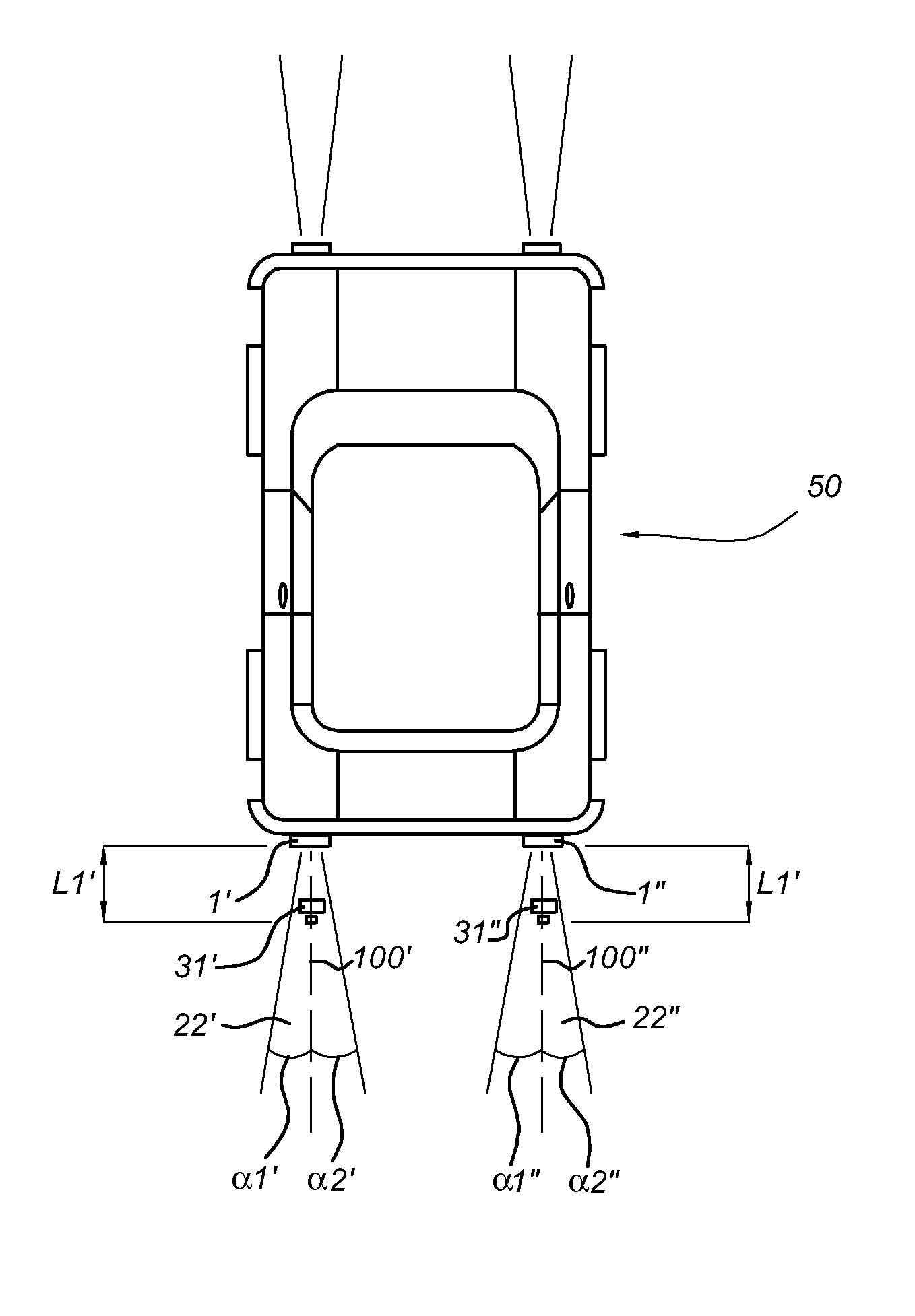
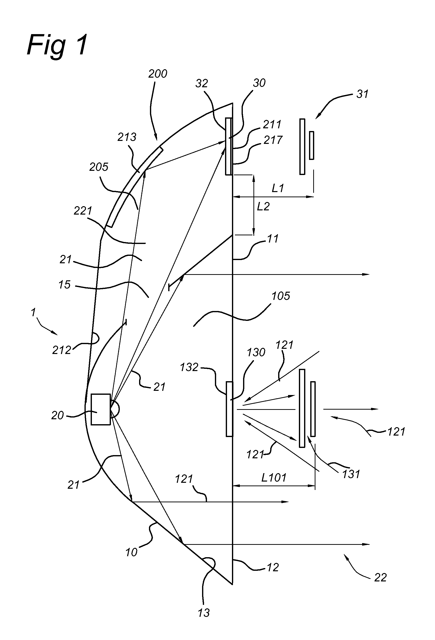
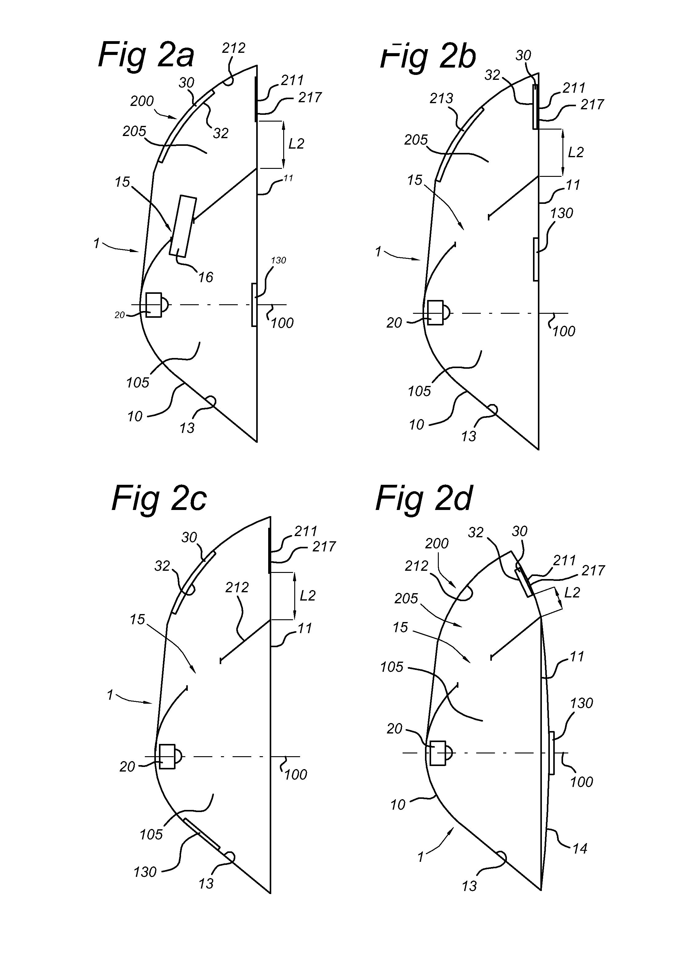
[0044]FIG. 1 schematically shows, in a side view, a car lighting unit or device 1 according to the invention. For the sake of clarity, peripheral equipment such as a source, a lamp holder, connectors, ballasts, optional sensors, etc, is not included in the schematic drawing(s). The lighting unit 1 comprises a reflector 10 and a light source 20 arranged to generate light 21. During use of the lighting unit 1, light source 20 generates light and the lighting units provide a beam 22. As known in the art, the reflector 10 circumferentially surrounds the light source 20. In this schematically shown embodiment, the reflector is a tapered body with a reflector opening 11, and the reflector 10 is arranged to reflect at least part of the light 21 from the light source 20 through the reflector opening 11. For instance, the reflector 10 may also be used as a collimator. Reflectors of this type are known in the art. The reflector 10 is not necessarily centro-symmetrical, but may have any tapere...


PUM


Abstract

The invention provides a car lighting unit comprising a reflector and a light source arranged to generate light. The reflector circumferentially surrounds the light source and has a reflector opening. The reflector is arranged to reflect at least part of the light from the light source through the reflector opening. The car lighting unit further comprises a source-related 3D hologram and a source-unrelated 3D hologram. The car lighting unit is 5 constructed to generate a beam of light and a source-related holographic 3D image, using light from the light source, during operation of the lighting unit, and a source-unrelated 3D holographic image when the lighting unit is not in operation.

Description

FIELD OF THE INVENTION[0001]The present invention relates to a car lighting unit comprising a reflector and a light source, the car lighting unit further comprising a hologram.BACKGROUND OF THE INVENTION[0002]Use of holograms in lighting applications is known in the art. For instance, U.S. Pat. No. 5,497,251 discloses a hologram structure for use in a holographic center high-mounted stoplight system for a vehicle. The hologram structure includes an illumination source for providing a reconstruction beam, a first array of non-overlapping hologram cells and non-hologram cells, and a second array of non-overlapping hologram cells and non-hologram cells. Each hologram cell of the first array produces a specular image that is viewable in a first predetermined angular field pursuant to diffraction of a portion of the reconstruction beam, and each hologram cell of the second array produces a diffuse image that is viewable in a second predetermined angular field pursuant to diffraction of a...

Claims


Application Information

Patent Timeline
Patent Type & Authority Applications(United States)
IPC IPC(8): F21S8/10F21W107/10
CPCB60Q1/0017F21S43/00F21V7/0025G03H1/30G03H2001/0055G03H2001/2231G03H2001/2234G03H2001/226G03H2001/262G03H2223/16G03H2227/06G03H1/2286G03H1/24G03H2210/30G03H1/2202F21V5/002F21S43/40F21S43/26F21S43/31F21S43/14F21S43/235B60Q1/535F21V7/00G03H1/22
Inventor OOMEN, EMMANUEL WILHELMUS JOHANNES LEONARDUSWANG, LINGLI
Owner KONINKLIJKE PHILIPS ELECTRONICS NV
Why Eureka
Try Eureka