
Mobile communication terminal

a mobile communication and terminal technology, applied in the field of mobile communication terminals, can solve problems such as increasing power consumption

Inactive Publication Date: 2010-12-02
KK TOSHIBA
View PDF2 Cites 27 Cited by
  • Summary
  • Abstract
  • Description
  • Claims
  • Application Information

AI Technical Summary

Benefits of technology

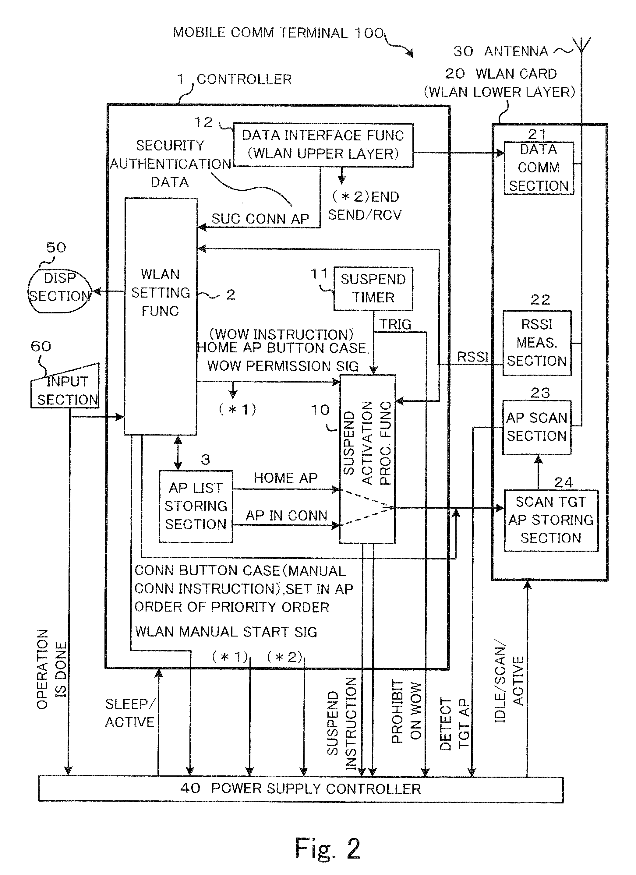
[0013]Exemplary embodiments of the invention provides a mobile communication terminal which comprises a first section which scans the access points to search for a targeted access point when activated and senses strength of signals received from the access points while scanning, wherein the first section is activated periodically, a second section which performs radio communication after the targeted access point is detected by means of the scanning by the first section, and a controller which specifies the home access point as the targeted access point upon identifying that the mobile communication terminal is out of a service area of the targeted access point from the signal strength sensed by the first section, and supplies the second section with power after the home access point is detected by means of the scanning.

Problems solved by technology

Thus, there is a conflicting problem in that an increase of the number of APs entered in the scan target AP list enhances a user's convenience but causes an increase of power consumption.

Method used


Image

  • Mobile communication terminal
  • Mobile communication terminal
  • Mobile communication terminal

Examples


Embodiment Construction

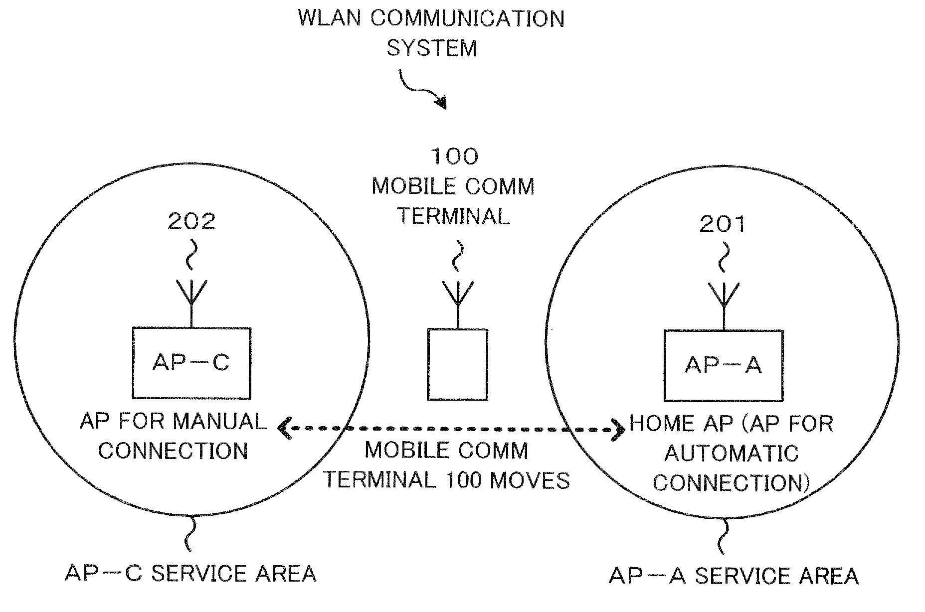
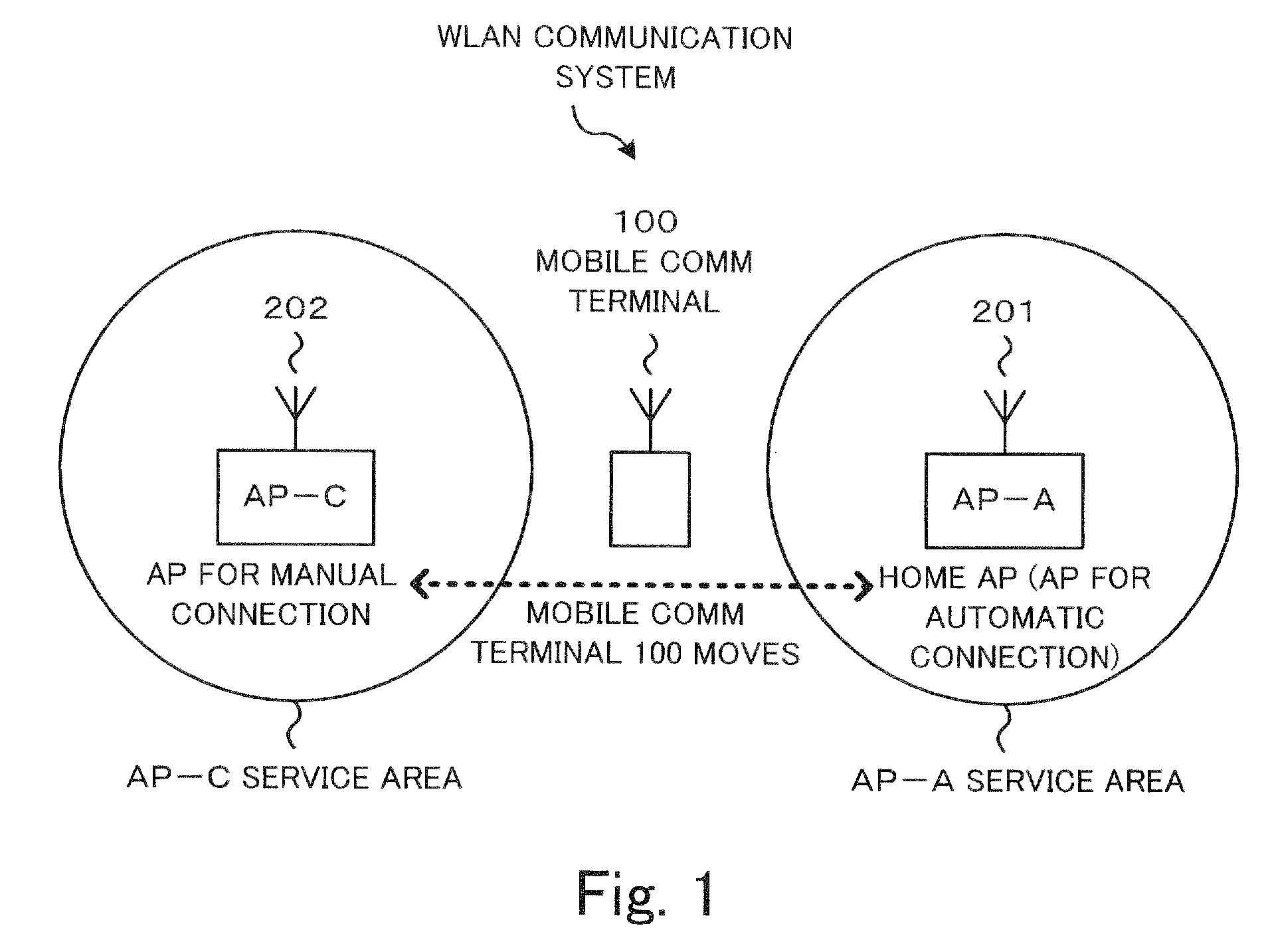
[0021]FIG. 1 shows an exemplary system diagram of WLAN communication of an embodiment. FIG. 1 shows two access points AP201 and AP202 as examples, and shows a mobile communication terminal 100 which moves between the two APs. Assume that AP201 (AP-A) is registered in the mobile communication terminal 100 as an AP for automatic activation (home AP). The mobile communication terminal 100 performs an AP scanning operation for AP 201, and automatically activates units and functions to make a wireless communication upon moving into the service area of AP201 (AP-A).

[0022]Further, after the mobile communication terminal 100 moves into a service area of AP202 (AP-C), a user can manually connect the mobile communication terminal 100 to AP202 (AP-C) so as to communicate with AP202.

[0023]Then, an internal configuration of the mobile communication terminal 100 will be explained. FIG. 2 is an exemplary block diagram of the mobile communication terminal 100. The mobile communication terminal 100 ...


PUM


Abstract

According to one embodiment, a mobile communication terminal comprises a first section which scans the access points to search for a targeted access point when activated and senses strength of signals received from the access points while scanning, wherein the first section is activated periodically, a second section which performs radio communication after the targeted access point is detected by means of the scanning by the first section, and a controller which specifies the home access point as the targeted access point upon identifying that the mobile communication terminal is out of a service area of the targeted access point from the signal strength sensed by the first section, and supplies the second section with power after the home access point is detected by means of the scanning.

Description

CROSS REFERENCE TO RELATED APPLICATIONS[0001]This application is based upon and claims the benefit of priority from the prior Japanese Patent Application No. 2009-126928 filed on May 26, 2009;the entire contents of which are incorporated herein by reference.BACKGROUND[0002]1. Field[0003]The present invention relates to a mobile communication terminal.[0004]2. Description of the Related Art[0005]A terminal device complying with a Wake On Wireless LAN system, in a waiting condition, can perform an AP scanning operation for searching for an access point (AP) whose identification information is stored in the terminal device. Upon moving into a service area of an AP and thus detecting the AP by means of the scanning operation, the terminal device can automatically activate other necessary portions of the terminal device and perform a wireless LAN (WLAN) communication process so as to enhance a user's convenience.[0006]For such an automatic activation system, a method for controlling powe...

Claims


Application Information

Patent Timeline
Patent Type & Authority Applications(United States)
IPC IPC(8): H04W36/00H04W40/00
CPCH04W48/16Y02D70/142H04W88/02H04W52/028Y02D30/70
Inventor TAKAMUNE, AKIRA
Owner KK TOSHIBA
Learn More