

Tissue retractor
a retractor and tissue technology, applied in the field of surgical procedures, can solve the problems of no gingival sulcus permit to reach, ineffective use of cords or retractors for maxillary bone intervention, and serious disadvantage of tools, so as to reduce the additional risk of injury
- Summary
- Abstract
- Description
- Claims
- Application Information
AI Technical Summary
Benefits of technology
Problems solved by technology
Method used
Image

Examples
first embodiment
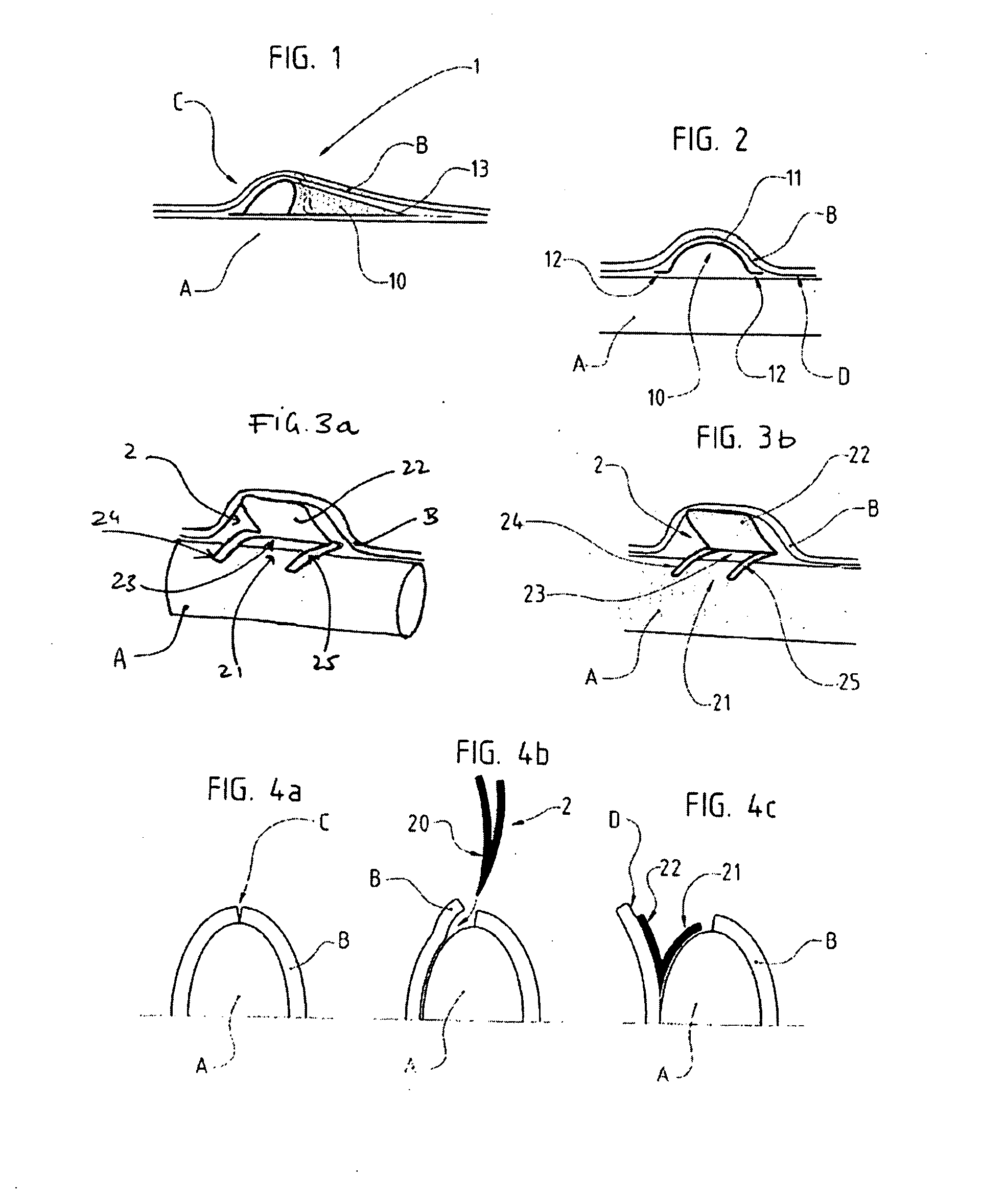
[0033]In a tissue retractor 1 according to the invention, as shown in FIGS. 1 and 2, it is comprised of a blade 10 having, in its stable shape, a concave curve conferring same a cross-section having the shape of a portion of a cylinder.
[0034]In this embodiment, the curve of blade 10 permits to obtain a tunnel-shaped tissue retractor 1, the plain portion 11 of the blade 10 entering into contact with the gingival tissue B in order to lift it, the two side ends 12 of the blade 10 resting on the maxillary bone A.
[0035]It will be understood that the insertion and the placing of such a tissue retractor 1 are then facilitated by the elastic properties of blade 10. Since the latter is flexible, it will be possible to flatten it in order to slide it into the incision C made in the gingival tissue B. By releasing the pressure on the blade 10, the latter will recover its stable shape while lifting the gingival tissue B and while making the maxillary bone A accessible to the practitioner.
[0036]...
second embodiment
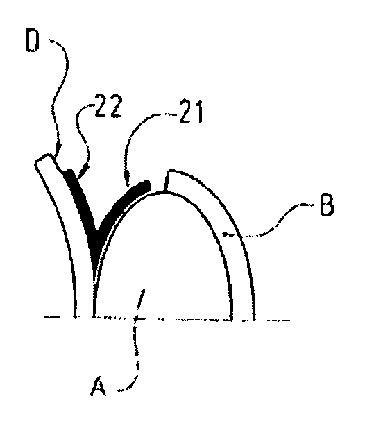
[0042] shown in FIGS. 3A and 3B, a tissue refractor 2 according to the invention can be in the form of a V-folded blade 20 so as to form two portions 21 and 22, conferring to the unit a stable open-pliers shape.
[0043]According to a first variant of this second embodiment, as shown in FIG. 3A, the blade 20 includes two partial side cut-outs defining two thin leaves 24 and 25 on both sides of the central body of the blade 20. By folding the two thin leaves 24 and 25 with respect to the central body of the blade 20, one obtains two portions 21 and 22, the portion 21 comprised of the two thin leaves 24 and 25, maintaining and pushing the tissue retractor 2 away from the maxillary bone A, the portion 22 permitting to push the gingival tissue B to a distance away from the area to be treated. The opening 23 defined by the space between the two thin leaves 24 and 25 allows the practitioner to reach the surface of the maxillary bone A to be treated.
[0044]According to a second variant of this...
third embodiment
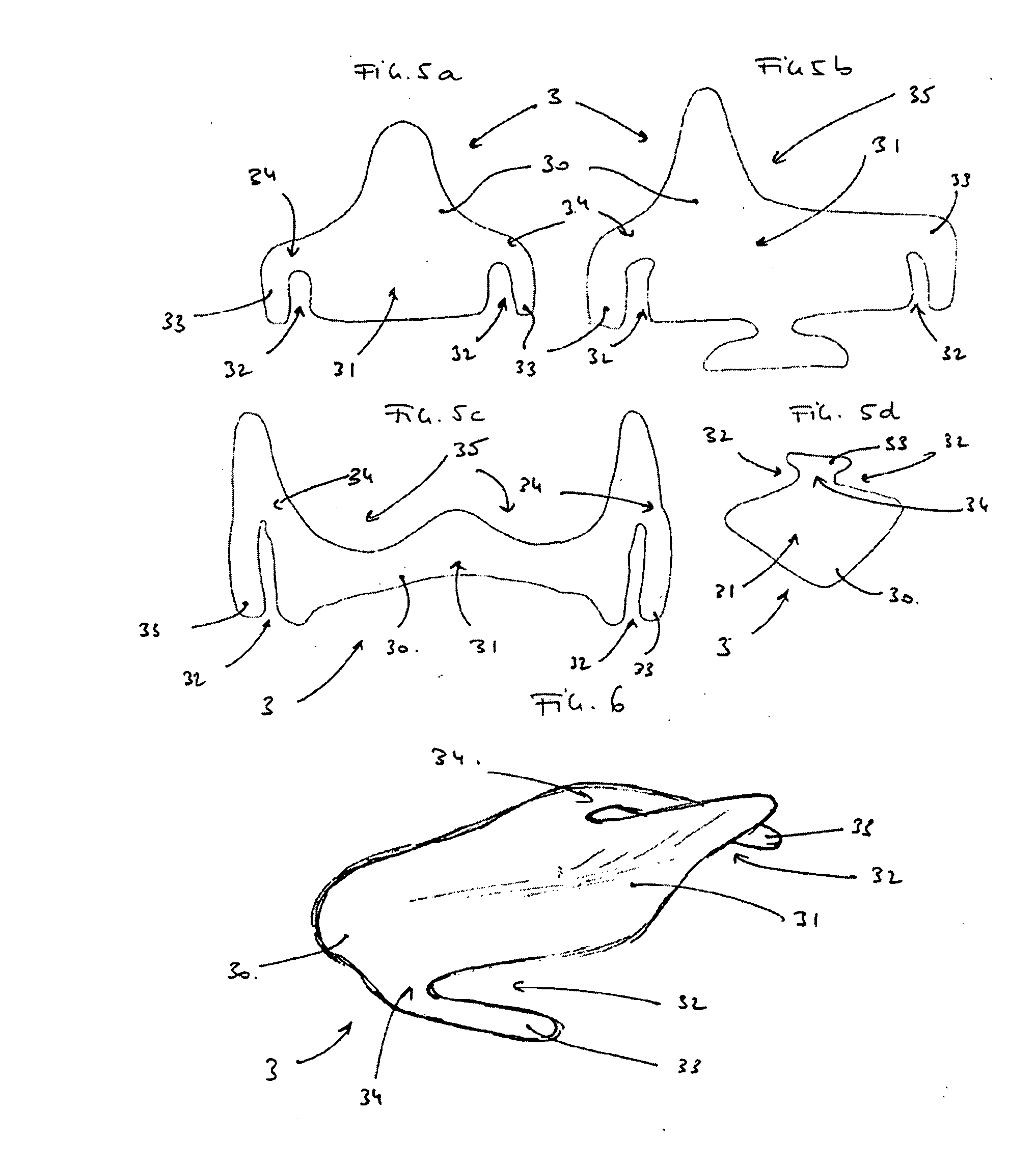
[0055]A third embodiment as shown in the diagrams of FIGS. 5A, 5B, 5C, 5D and 6 permits to solve this problem by providing a tissue retractor 3 defined by a blade 30 including a central body 31 and at least one cut-out 32 permitting to delimit, on the periphery of this central body 31, at least one fin 33.
[0056]The shape of blade 30 is advantageously dictated by the practitioner's needs. This variability is shown by the various alternative shapes of FIGS. 5A to 5D.
[0057]The shape and the dimensioning of the cut-outs 32 advantageously permit to define one or several areas 34 with a lesser torsion strength of the material the blade 30 is made of, in order to permit a varying positioning of the wing or wings 33 with respect to the central body 31, namely by a folding action at the level of these areas 34, This action can advantageously be carried out in situ by the practitioner upon insertion of the retractor 3 between the maxillary bone A and the gingival tissue B, in order to achieve...
PUM
 Abstract
Description
Claims
Application Information