Supercharge Your Innovation With Domain-Expert AI Agents!

Multi-Stage Multi-Tube Shell-and-Tube Reactor

a reactor and multi-tube technology, applied in indirect heat exchangers, chemical/physical/physicochemical processes, lighting and heating apparatus, etc., can solve the problem that traditional shell-and-tube reactors do not have enough heat transfer capability to keep these reaction systems, and achieve efficient heat transfer and small diameter

Inactive Publication Date: 2010-12-09
HONEYWELL INT INC
View PDF15 Cites 16 Cited by
  • Summary
  • Abstract
  • Description
  • Claims
  • Application Information

AI Technical Summary

Benefits of technology

[0018]The tubes used for the reaction zone are preferably larger in diameter to provide room for catalyst packing. The int

Problems solved by technology

Traditional shell-and-tube reactors do not have enough heat transfer capability to keep these reaction systems at optimal operating conditions.

Method used


Image

  • Multi-Stage Multi-Tube Shell-and-Tube Reactor
  • Multi-Stage Multi-Tube Shell-and-Tube Reactor
  • Multi-Stage Multi-Tube Shell-and-Tube Reactor

Examples


Embodiment Construction

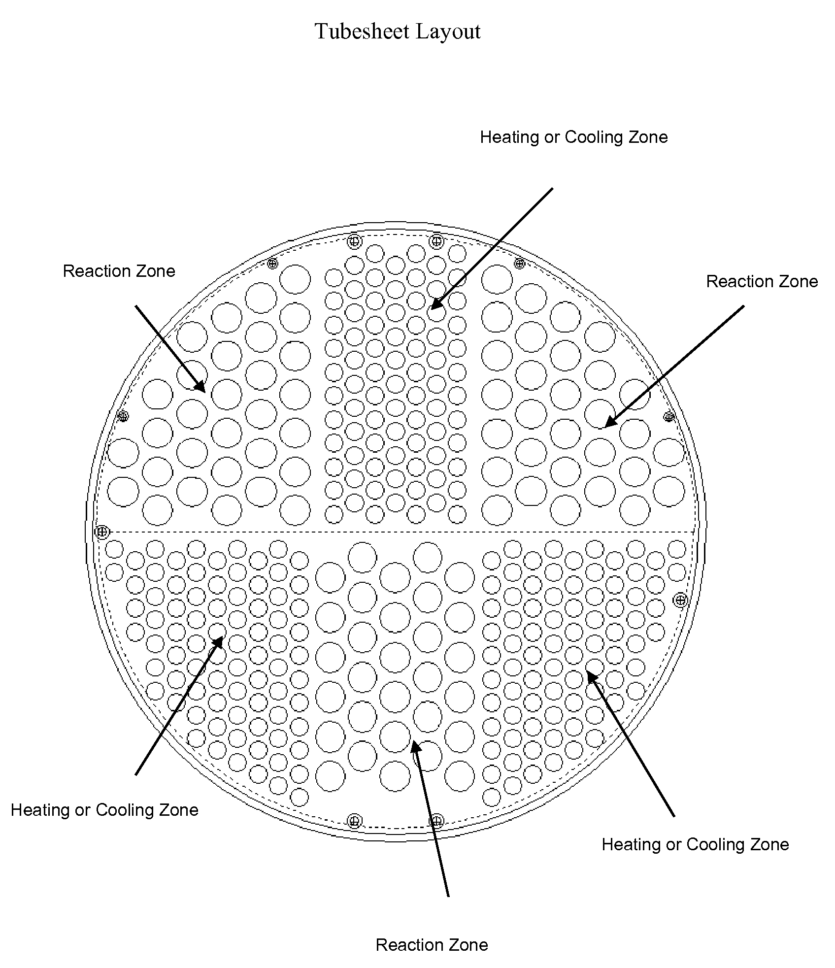
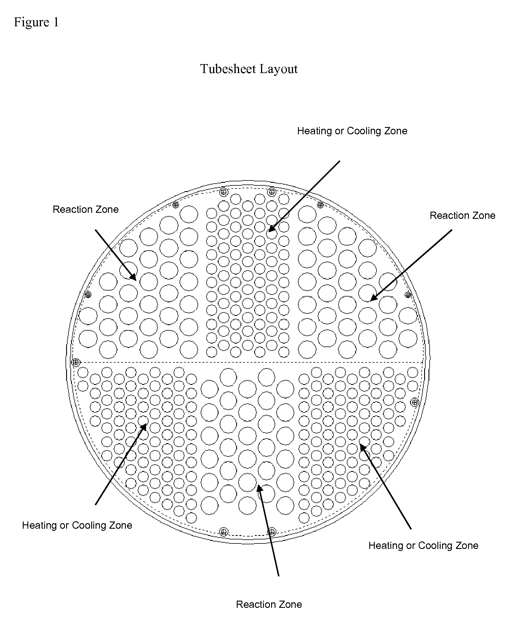
[0041]The present invention is a shell-and-tube reactor that has at least two different types of zones which can be used for either reacting or temperature control (heating / cooling) depending on the system's needs.

[0042]Referring in detail to the drawings FIG. 1 shows an embodiment one tubesheet used in the reactor of the present invention having three reaction zones separated by three temperature control (heating / cooling) zones.

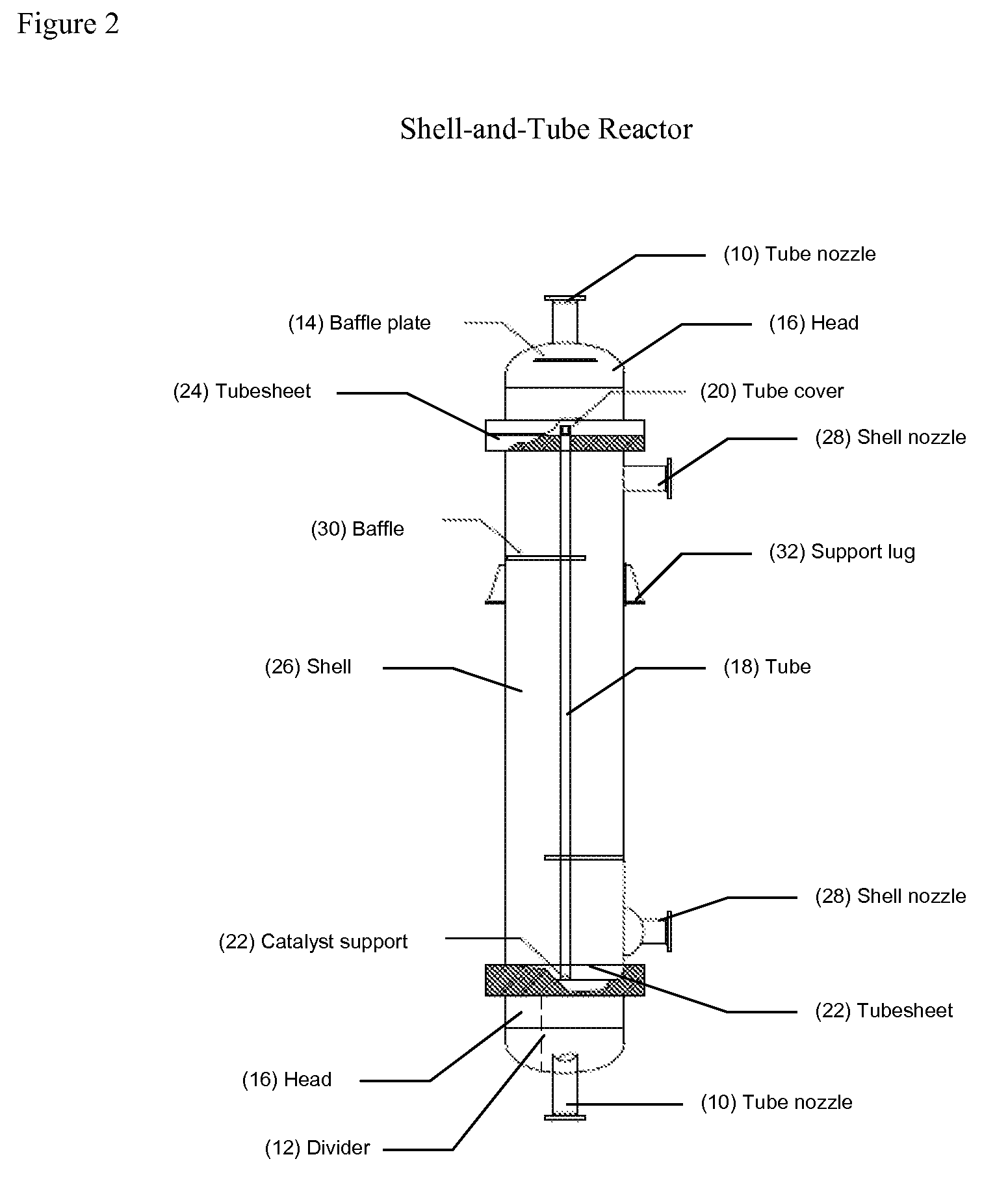
[0043]FIG. 2 shows a vertical shell-and-tube reactor with parts normally associated with such equipment. The process fluids will enter the reactor through a tube nozzle (10) shown at the top of the figure. The dividers (12) inside the head distribute the fluid to the correct heating / cooling or reaction zone depending on the system's needs. A baffle plate (14) will slow and distribute the process fluids as they pass through a head (16) and enter the tubes (18). Tube covers (20) and catalyst supports (22) will keep the catalyst confined to the tube. Typically,...


PUM


Abstract

A multi-stage, multi-tube, shell-and-tube reactor which contains reaction zones and interstage temperature control (cooling / heating) zones in series. The reactor has at least two types of zones which both contribute to removing or supplying heat to the system depending on the system's need. The reactor will have a group of reaction zones which contain tubes packed with catalyst to progress the reaction and remove or supply heat simultaneously. There are also a number of interstage temperature control (cooling / heating) zones which are designed to supply or remove heat to or from the system. The positioning, number, and design of the zones will depend on the amount of temperature control desired and exothermic or endothermic nature of the processes to be conducted in the reactor.

Description

FIELD OF THE INVENTION[0001]The present invention relates to shell-and-tube catalytic reactors having improved heating or cooling capabilities for use with exothermic or endothermic chemical reactions.BACKGROUND OF THE INVENTION[0002]Generally, a shell-and-tube catalytic reactor is a type of reactor which is used to efficiently remove reaction heat. In some uses of these reactors, a catalyst is filled in a plurality of reaction tubes; a reaction fluid (gas and / or liquid) into the reaction tubes to cause a chemical reaction for obtaining a desired product; and a heat transfer medium is circulated through the reactor shell such that the chemical reaction can occur under controlled thermal conditions. Shell and tube reactors typically include a number of reaction tubes held in place in the shell by one or more tubesheets; shell nozzles are used for introducing and withdrawing the heat transfer medium; tube nozzles are used for introduction of reactants into the reaction tubes and for w...

Claims


Application Information

Patent Timeline
IPC IPC(8): F28F9/02
CPCB01J8/067B01J2208/00221B01J2208/0023F28F2009/226F28F9/0202F28F9/0265F28F2210/08F28D7/1638
Inventor CHIU, YUONCOTTRELL, STEPHEN A.HORWATH, RICHARD DURICKKOPKALLI, HALUK
Owner HONEYWELL INT INC
Features
  • R&D
  • Intellectual Property
  • Life Sciences
  • Materials
  • Tech Scout
  • Unparalleled Data Quality
  • Higher Quality Content
  • 60% Fewer Hallucinations
Learn More