Electric connection box

a technology of electric components and connection boxes, which is applied in the directions of electrical apparatus casings/cabinets/drawers, coupling device connections, transportation and packaging, etc., can solve the problems of wet contact of the connectors of electric components

Inactive Publication Date: 2010-12-09
FURUKAWA ELECTRIC CO LTD +1
View PDF21 Cites 22 Cited by
  • Summary
  • Abstract
  • Description
  • Claims
  • Application Information

AI Technical Summary

Problems solved by technology

Under the configurations of the above-mentioned electric connection boxes, however, rainwater enters the interiors of the electric connection boxes and reaches a component-mounting surface on which the electric components are mounted on the base blocks, such that the contacts of the connectors of the electric components become wet to cause thei

Method used


Image

  • Electric connection box
  • Electric connection box
  • Electric connection box

Examples


first embodiment

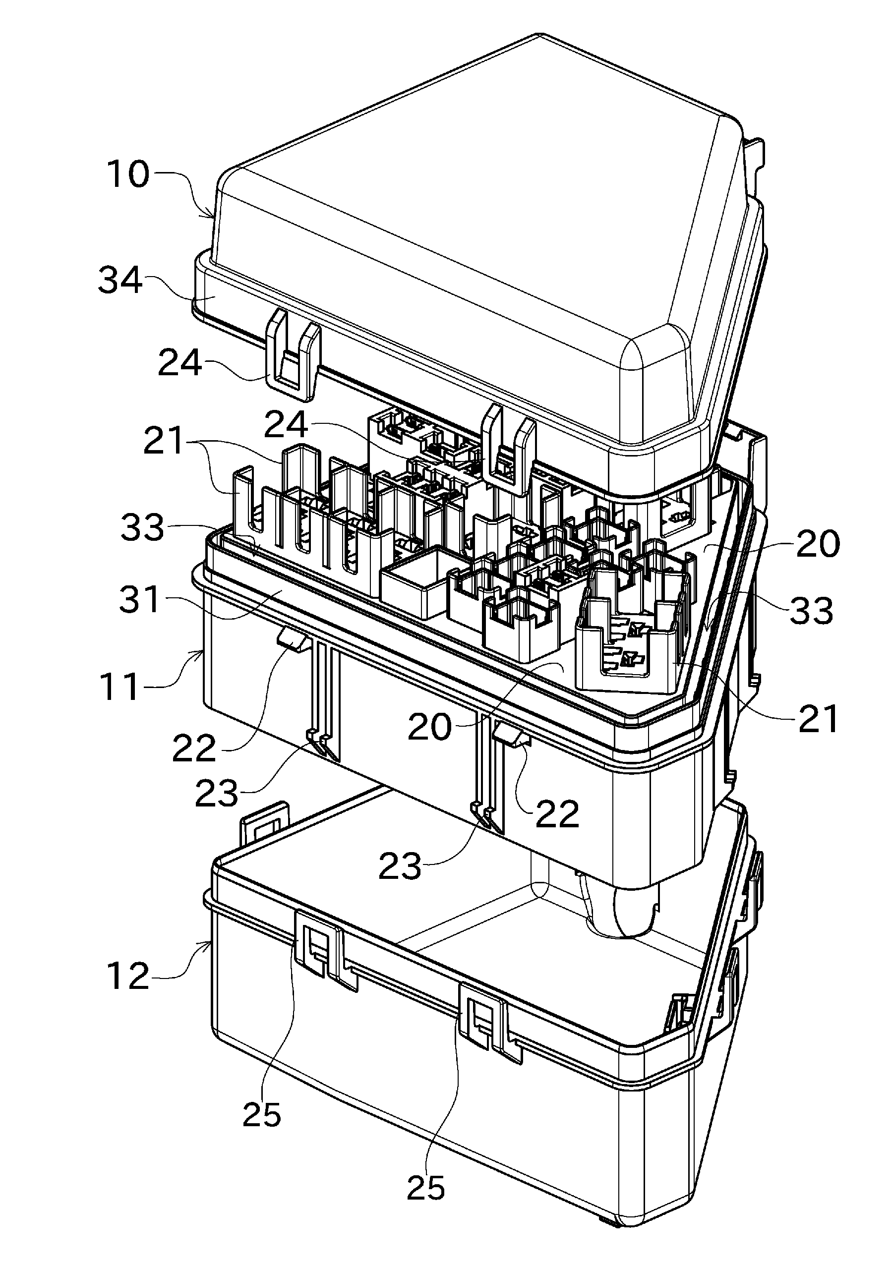
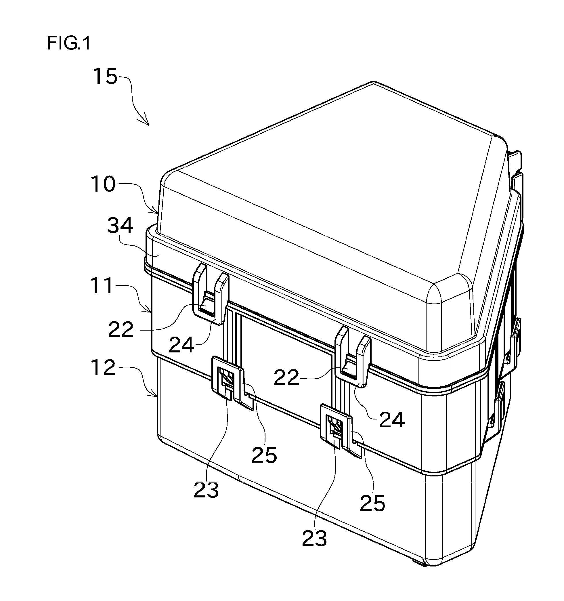
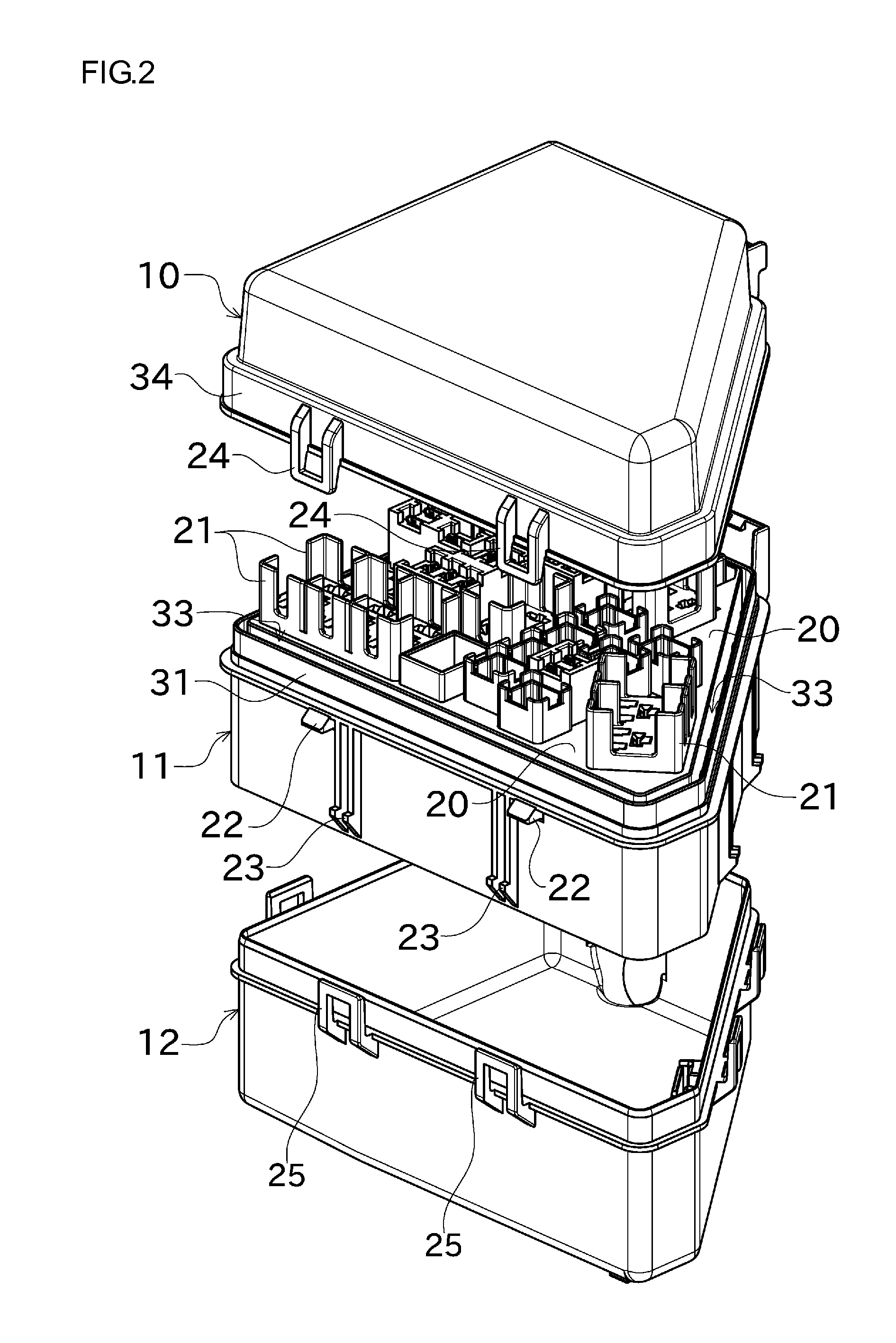
[0040]FIG. 1 is a perspective view showing the outer appearance of an electric connection box according to the present invention.

[0041]As shown in FIG. 1, an electric connection box 15 is disposed at the upper portion of an engine room of an automobile, which includes an upper cover 10, a base block 11 and a lower cover 12. The base block 11 has a generally trapezoidal shape when viewed on the plane.

[0042]A plurality of locking hooks 22 is mounted along the upper end portion of the base block 11, and also, a plurality of locking hooks 23 is mounted along the lower end portion of the base block 11. On the other hand, a plurality of locking fitting parts 24 is disposed along the lower end portion of the upper cover 10 in corresponding relation with the plurality of locking hooks 22, and also, a plurality of locking fitting parts 25 is disposed along the upper end portion of the lower cover 12 in corresponding relation with the plurality of locking hooks 23. Thus, the upper cover 10 an...

second embodiment

[0065]Hereinafter, another preferred embodiment of the present invention will be described with reference to FIG. 4. FIG. 4 is a perspective view showing the main parts of the base block of an electric connection box according to the present invention.

[0066]According to the second embodiment of the present invention, as shown in FIG. 4, a drain groove 50 having a ‘V’-shaped section is formed on the component-mounting surface 20 located on the top surface of the base block 11. The drain groove 50 is slantly formed to a height reducing from the center of the component-mounting surface 20 toward the peripheral section (the water-discharging hole 33) thereof. As a result, the water existing in the drain groove 50 is induced to the water-discharging hole 33.

[0067]Under the above-mentioned configuration of the second embodiment of the present invention, even when the water enters the component-mounting surface 20, the water is rapidly sent to the water-discharging hole 33 through the drai...


PUM


Abstract

An electric connection box for an automobile effectively prevents entry of water into the box and allows water entered the box to be easily discharged. The electric connection box has a base block (11) having a component-mounting surface (20) on which electric components such as relays (30) are mounted, and also has an upper cover (10) for covering the electric components. The component-mounting surface (20) is located above the lower end of a peripheral section (34) of the upper cover (10). On the outer periphery of the base block (11) is formed a first peripheral wall (31) fitting to the peripheral section (34) of the upper cover (10). The first peripheral wall (31) is located inside the peripheral section (34) of the upper cover (10). The upper end of the first peripheral wall (31) is located above the lower end of the peripheral section (34) of the upper cover (10). The component-mounting surface (20) is located above the upper end of the first peripheral wall (31).

Description

TECHNICAL FIELD[0001]The present invention relates to an electric connection box for an automobile which has a plurality of electric components mounted therein.BACKGROUND ART[0002]Generally, an electric connection box to be mounted within an engine room of an automobile is known as the type having electric components like relays or fuses disposed on a base block, the electric components being covered with an upper cover. Also, the electric connection box is known as another type having a wire harness connected to the electric components in such a manner as to be drawn from the underside of the base block, the wire harness being covered with a lower cover.[0003]Under the configurations of the above-mentioned electric connection boxes, however, rainwater enters the interiors of the electric connection boxes and reaches a component-mounting surface on which the electric components are mounted on the base blocks, such that the contacts of the connectors of the electric components become...

Claims


Application Information

Patent Timeline
IPC IPC(8): H05K5/00
CPCB60R16/0238H05K7/026H02G3/088
Inventor AOKI, OSAMUHOSODA, MICHIESAWAKI, YOSHIAKI
Owner FURUKAWA ELECTRIC CO LTD
Why Eureka
Try Eureka