
Keyswitch and keyboard

a keyswitch and keyboard technology, applied in the field of keyswitch and keyboard, can solve the problems of difficulty in corresponding span control, inconvenient operation for users, and failure to meet the design standard of the vertical surface of the reversed l-shaped structure, so as to prevent the drawback of the vertical surface, the height of the keyswitch can be controlled better, and the effect of flexible utilization

Inactive Publication Date: 2010-12-09
DARFON ELECTRONICS CORP
View PDF5 Cites 0 Cited by
  • Summary
  • Abstract
  • Description
  • Claims
  • Application Information

AI Technical Summary

Benefits of technology

[0009]Therefore, an objective of the invention is to provide a base applied to a keyswitch and a keyboard. The invention adds a protrusion portion to a sliding portion of the base. The protrusion portion controls the span by utilizing the relation between the protrusion portion and the step portion instead of the vertical surface of the conventional step portion, so as to solve the problem that the span is difficult to be controlled in the prior art.

Problems solved by technology

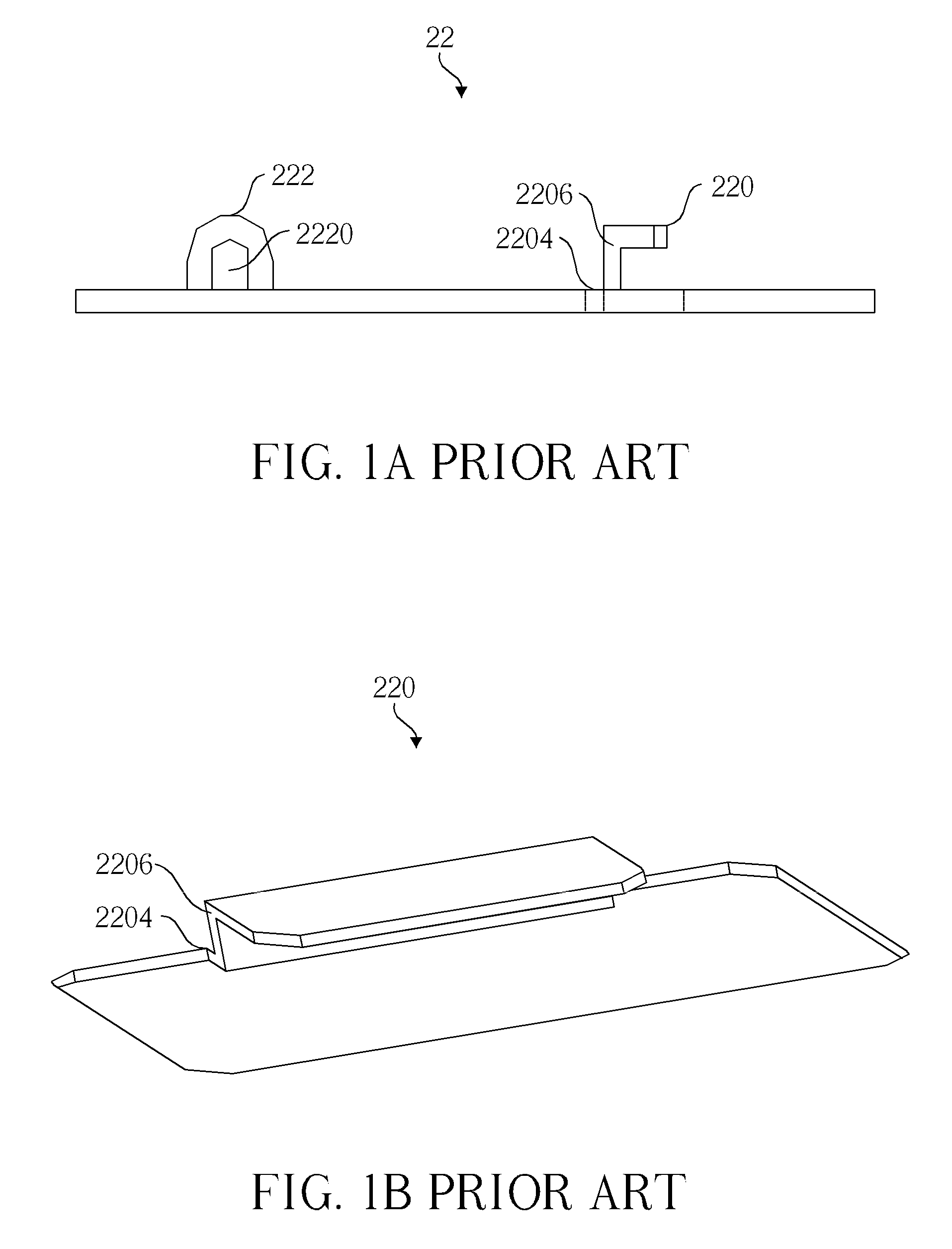
When the step portion 220 is manufactured by a series of manufacturing processes, a vertical surface of the reversed L-shaped structure 2206 may fail to meet the design standard due to the mold design or a long term wearing of the mold.
If the reversed L-shaped structure 2206 tilts, the span will be difficult to be controlled correspondingly.
Furthermore, in practical application, if each span on the base 22 of the keyboard is different from each other, each height of the keyswitch will be also different from each other, such that it is inconvenient for a user in operation.

Method used


Image

  • Keyswitch and keyboard
  • Keyswitch and keyboard
  • Keyswitch and keyboard

Examples


first embodiment

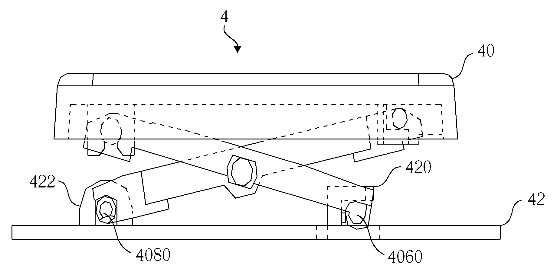
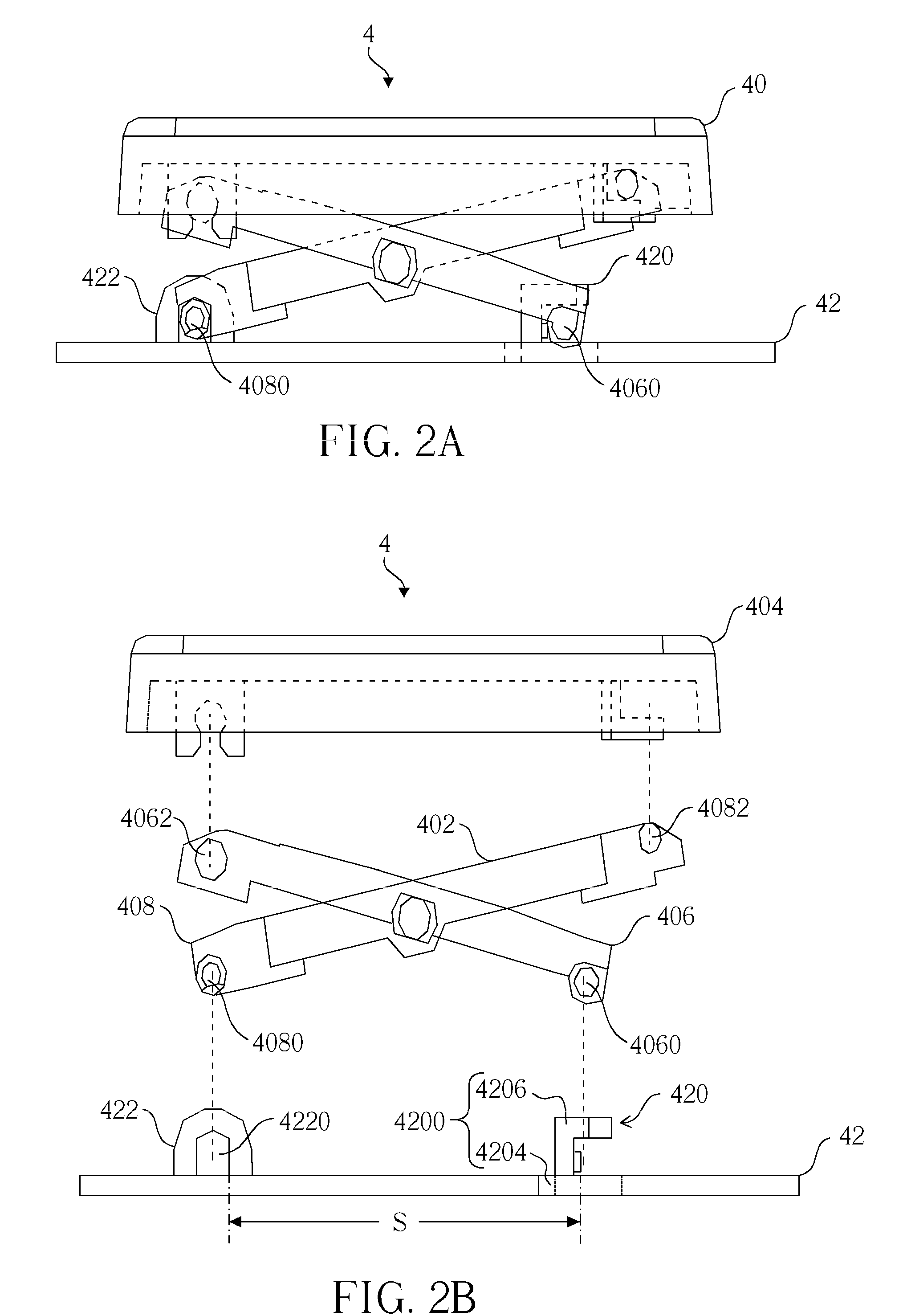
[0033]Referring to FIG. 2A and FIG. 2B, FIG. 2A is a schematic diagram illustrating a keyswitch 4 according to the invention, and FIG. 2B is an exploded view illustrating the keyswitch 4 of FIG. 2A.

[0034]As shown in FIG. 2A and FIG. 2B, the keyswitch 4 comprises a keyswitch member 40 and a base 42. The keyswitch member 40 comprises a support structure 402 and a keycap 404. The support structure 402 comprises a first support member 406 and a second support member 408. A first connecting portion 4060 is disposed on one end of the first support member 406, and a third connecting portion 4062 is disposed on the other end of the first support member 406. A second connecting portion 4080 is disposed on one end of the second support member 408, and a fourth connecting portion 4082 is disposed on the other end of the second support member 408.

[0035]In this embodiment, the first support member 406 is pivotally connected to the second support member 408 in a cross way, the third connecting po...

second embodiment

[0046]Referring to FIG. 9, FIG. 9 is a schematic diagram illustrating a keyboard 6 according to the invention. As shown in FIG. 9, the keyboard 6 comprises a plurality of keyswitches 60 and a base 62. The structure of each of the keyswitches 60 of the keyboard 6 is identical to the keyswitch 4 of the aforesaid embodiment, so the detailed description thereof will not be depicted here again, and referring to FIG. 2B as well while reading.

[0047]In this embodiment, each of the keyswitch members 60 comprises a support structure and a keycap and the structure thereof is identical to the first embodiment, so it will not be depicted here again. The keyswitch members 60 are disposed on the base 62, and the structure of the base 62 is identical to the first embodiment, so it will not be depicted here again.

[0048]In practical application, when the base 62 is finished by a series of manufacturing processes, the protrusion portion can control the height of the keyswitch easily and steadily inste...


PUM


Abstract

A keyswitch includes a keyswitch member and a base. The keyswitch member includes a first connecting portion and a second connecting portion. The base includes a sliding portion and a fixing portion. The sliding portion is for adjusting a height of the keyswitch member. The sliding portion includes a step portion and a protrusion portion. The first connecting portion is movably disposed in the step portion. The step portion includes a flat structure and a reversed L-shaped structure. The protrusion portion is adjacent to the step portion. The protrusion portion restrains the first connecting portion from moving. The fixing portion is disposed on the base relative to the sliding portion. A hole is formed on the fixing portion. The second connecting portion is pivotally connected to the fixing portion via the hole.

Description

BACKGROUND OF THE INVENTION[0001]1. Field of the Invention[0002]The invention relates to a keyswitch and a keyboard and, more particularly, to a sliding portion of a base of a keyswitch, wherein the sliding portion has a step portion and a protrusion portion for controlling a height of the keyswitch.[0003]2. Description of the Prior Art[0004]Recently, many data processing devices, such as, personal computers, notebook computers, smart phones and so on, have been developed as technology progressing. Many input devices are also designed corresponding to the variety of the data processing devices. A keyboard is the most common input device in variety of personal computers and notebook computers.[0005]Referring to FIG. 1A, FIG. 1A is a schematic diagram illustrating a base 22 of a conventional keyboard. As shown in FIG. 1A, the base 22 comprises a step portion 220 and a fixing portion 222. A second connecting portion of a keyswitch member (not shown) can be movably disposed in the step ...

Claims


Application Information

Patent Timeline
Patent Type & Authority Applications(United States)
IPC IPC(8): H01H13/76H01H13/14
CPCH01H3/125H01H2237/00H01H13/705
Inventor WANG, YI-CHEN
Owner DARFON ELECTRONICS CORP
Learn More