Magnetic switch for food processor

a technology of magnetic switch and food processor, which is applied in the field of magnetic switch, can solve the problems of difficulty in cleaning and maintaining the pusher, and the device cannot be considered perfectly

Inactive Publication Date: 2010-12-09
CONAIR CORP
View PDF1 Cites 37 Cited by
  • Summary
  • Abstract
  • Description
  • Claims
  • Application Information

AI Technical Summary

Benefits of technology

[0007]The present invention relates to a magnetic switch for, inter alia, a food processor comprising a base from which a tower and a drive shaft extend. Within inside of the tower, near its top, are disposed four magnets that control an electrical contact in the base, which contact either enables or disables a motor disposed in the base. The drive shaft is adapted to receive various tools that rotate to process various food products. The food processor also comprises a bowl detachably mounted on the base, said bowl having means for securing to the base so as to hold it in a given position, and a bowl cover having a chute. The bowl cover also comprises means for locking to the bowl and four magnets, which magnets are aligned with the four magnets disposed within the top of the tower extending from the base of the food processor. A pusher is used to push products down the chute without any possible contact between a hand and a rotating tool. The pusher comprises an actuator that push down the magnets of the bowl cover, thus activating the magnets disposed in the tower. Once the tower magnets are activated, the electrical contact in the base enables the motor and allows the food processor to operate.

Problems solved by technology

The devices have to be fitted with a safety means because they can be very dangerous as tools are driven at high speed in the bowl and any contact with a rotating tool may result in serious injury.
However, the device cannot be considered perfectly because the contact can be actuated by placing a magnet inserting a pointed object into the orifice in the base when the bowl is not in position, thus rotating the drive shaft.
Finally, there may be difficulties in cleaning and maintaining the pusher, which is pushed upwards by a spring.

Method used


Image

  • Magnetic switch for food processor
  • Magnetic switch for food processor
  • Magnetic switch for food processor

Examples


Embodiment Construction

[0025]Reference will now be made in detail to embodiments of the invention that are illustrated in the accompanying drawings. Wherever possible, same or similar reference numerals are used in the drawings and the description to refer to the same or like parts or steps. The drawings are in simplified form and are not to precise scale. For purposes of convenience and clarity only, directional terms, such as top, bottom, up, down, over, above, below, left, and right may be used with respect to the drawings. These and similar directional terms should not be construed to limit the scope of the invention in any manner. The words “connect,”“couple,” and similar terms with their inflectional morphemes do not necessarily denote direct and immediate connections, but also include connections through mediate elements or devices.

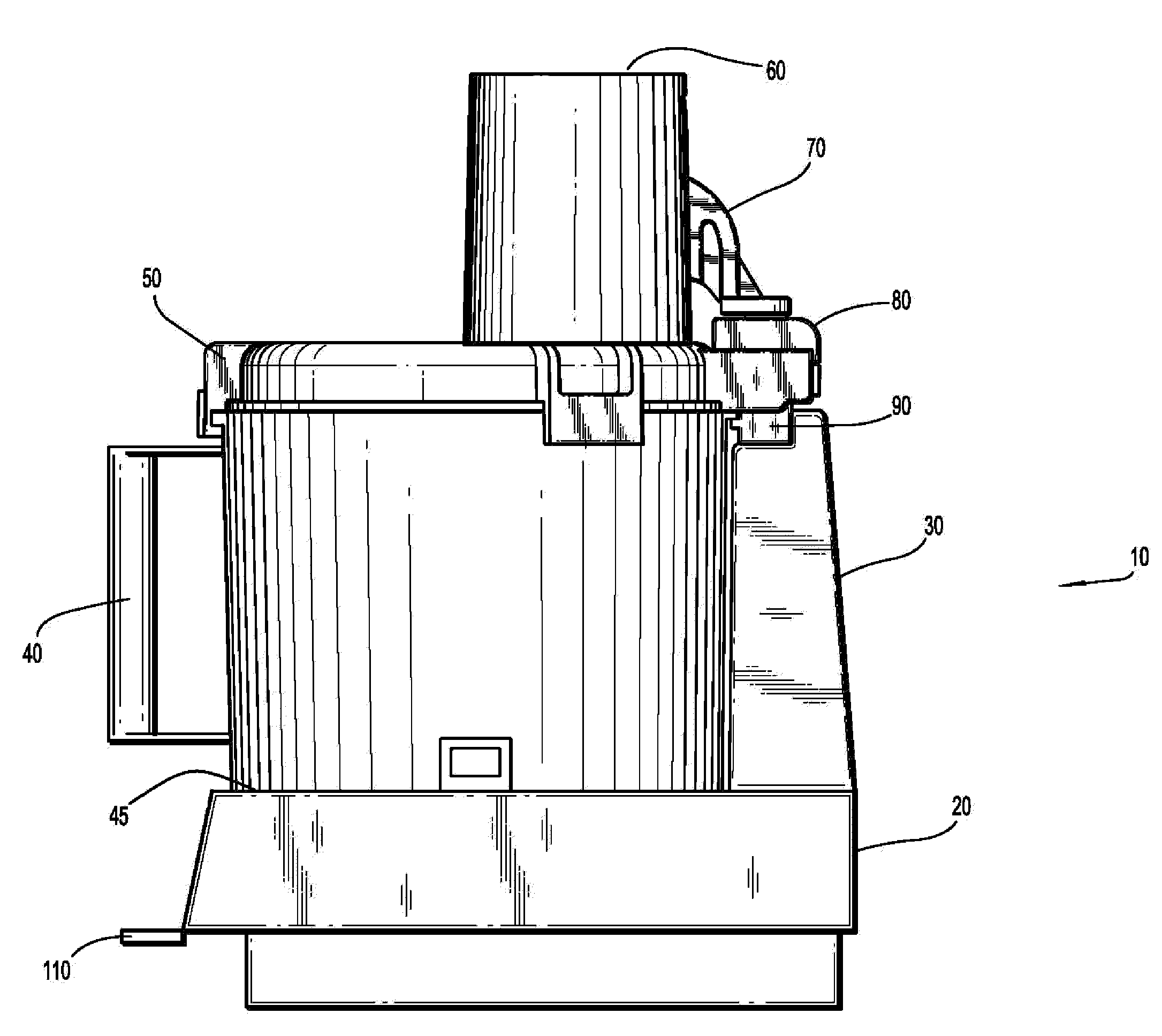
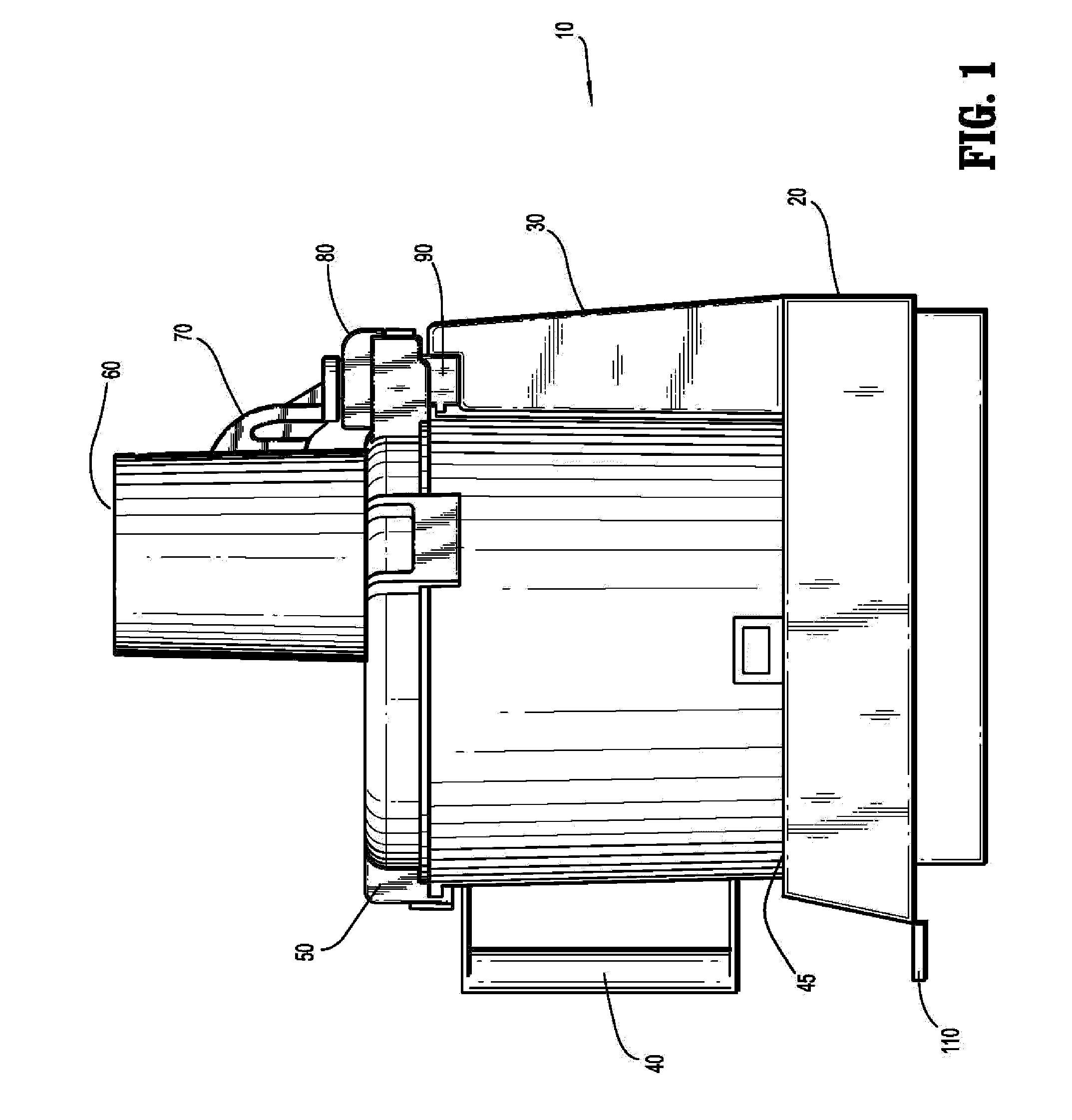
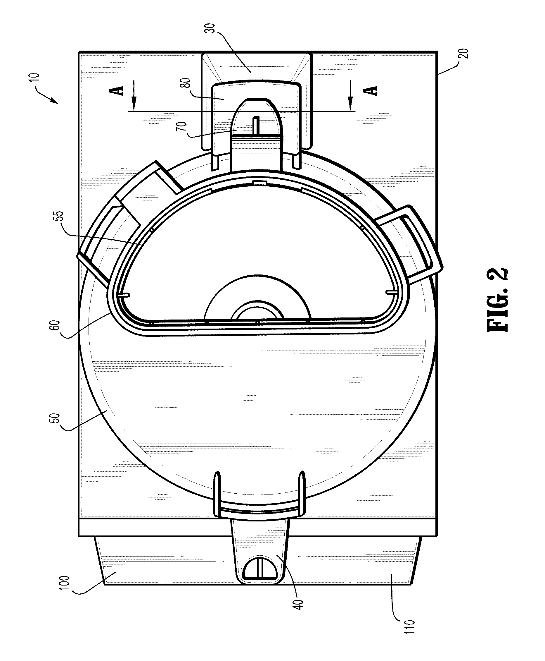
[0026]Referring to the drawings, FIGS. 1-3, in particular, food processor 10 comprises a base 20 from which a tower 30 and a drive shaft 160 (FIG. 6) extend. Base 20, as...


PUM


Abstract

A magnetic switch for, inter alia, a food processor, wherein, when a cover is locked on a bowl, which in turn is locked to a base, magnets are brought towards a magnetically controlled working contact connected in series in the supply circuit of a motor.

Description

FIELD OF THE INVENTION[0001]The invention relates to a magnetic switch for use more particularly though not exclusively for a food processor.BACKGROUND OF THE INVENTION[0002]Food processors conventionally comprise a base enclosing an electric motor having a shaft on which various tools such as knives or scrapers can be mounted. The drive shaft projects into a bowl adapted to enclose the tools and the products which have been or are being processed. In some cases the bowl is removably mounted on the base for ease in cleaning. The bowl is closed by a removable cover, the main purpose of which is to prevent material from being thrown out of the bowl. The devices have to be fitted with a safety means because they can be very dangerous as tools are driven at high speed in the bowl and any contact with a rotating tool may result in serious injury.[0003]The motor must be stopped either when the bowl is not properly fitted on the base or when the bowl is properly fitted on the base but the ...

Claims


Application Information

Patent Timeline
Patent Type & Authority Applications(United States)
IPC IPC(8): B02C23/00
CPCA47J43/0772A47J43/0794A47J43/0766A47J43/046
Inventor KRASZNAI, CHARLES Z.HU, ZHI HE
Owner CONAIR CORP
Why Eureka
Try Eureka