
Electronic ballast for a discharge lamp

a technology of electronic ballast and discharge lamp, which is applied in the direction of electrical equipment, instruments, light sources, etc., can solve the problems of large number of levels of complexity of electronic ballast, and achieve the effects of saving energy, convenient and inexpensive use, and convenient storag

Inactive Publication Date: 2010-12-09
OSRAM GMBH
View PDF9 Cites 0 Cited by
  • Summary
  • Abstract
  • Description
  • Claims
  • Application Information

AI Technical Summary

Benefits of technology

[0003]The object of the present invention is to provide an electronic ballast for a discharge lamp in accordance with the preamble of patent claim 1 which makes it possible to dim the discharge lamp with a compact and inexpensive design in order to be able to possibly thus save energy.
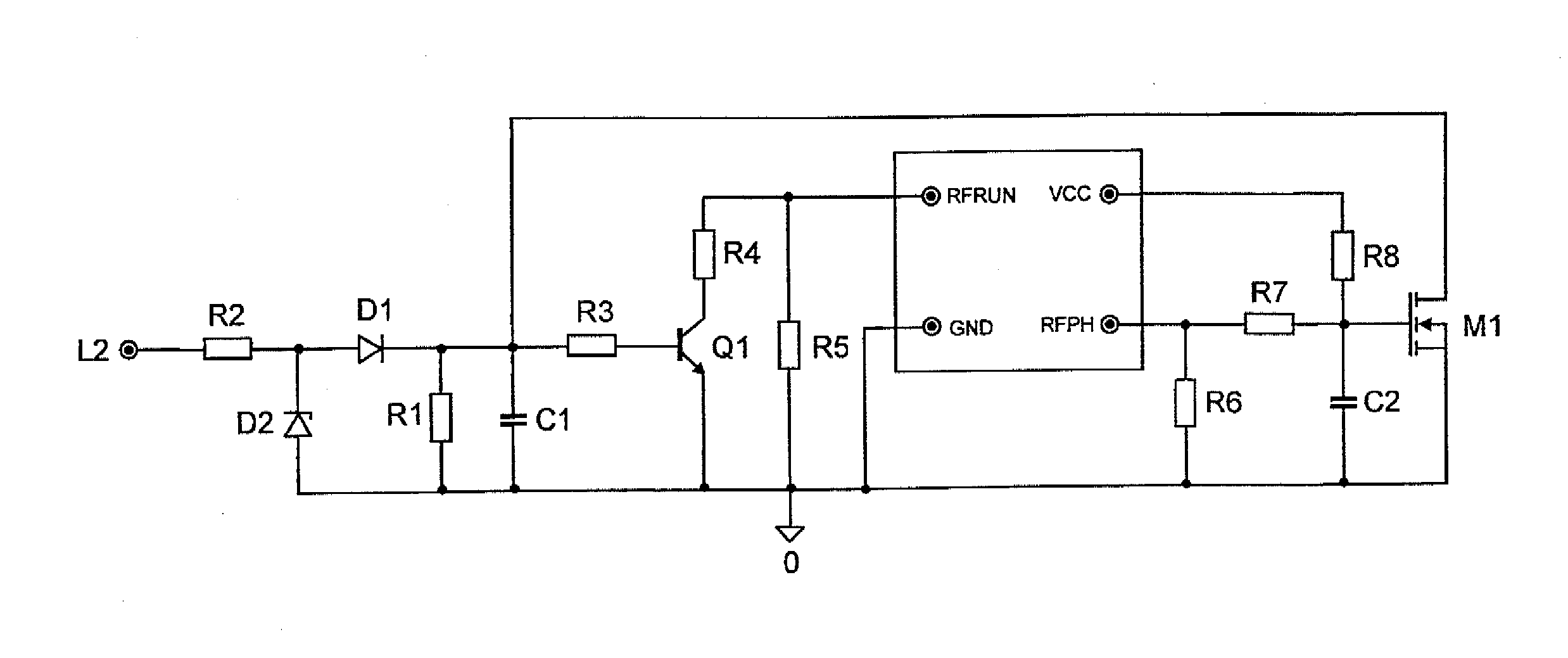
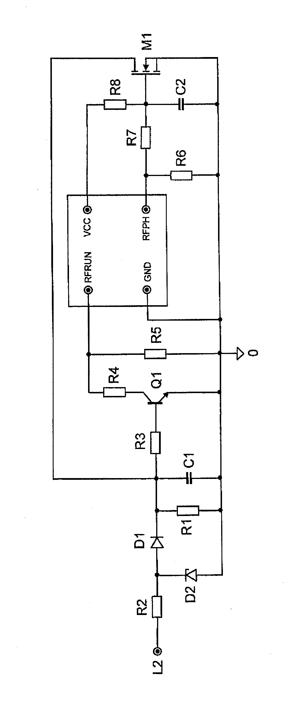
[0007]In a preferred embodiment, the electronic ballast includes a transistor, whose control input can be connected to the mains connection via the switch. The binary embodiment can therefore be implemented in a simple manner with a transistor, i.e. a component part which is particularly readily available and inexpensive. Then, a circuit can be influenced by the transistor, which circuit determines the potential at the control input of the control ASIC.

Problems solved by technology

There are electronic ballasts with a large number of levels of complexity.

Method used


Image

  • Electronic ballast for a discharge lamp
  • Electronic ballast for a discharge lamp

Examples


Embodiment Construction

[0003]The object of the present invention is to provide an electronic ballast for a discharge lamp in accordance with the preamble of patent claim 1 which makes it possible to dim the discharge lamp with a compact and inexpensive design in order to be able to possibly thus save energy.

[0004]This object is achieved by an electronic ballast for a discharge lamp having the features of the preamble of patent claim 1 by virtue of the features of the characterizing clause of patent claim 1.

[0005]The electronic ballast is connected to a switch via a single-pole terminal, with different potentials being determined at different positions of said switch, which potentials are present at a specific control input of the control ASIC. This control input is characterized by the fact that the potential present across it sets the operating frequency of the control ASIC when driving the discharge lamp, i.e. the operating frequency above which the power is defined during operation (after the switch-on...


PUM


Abstract

An electronic ballast arrangement for a discharge lamp is provided. the electronic ballast arrangement may include an electronic ballast for a discharge lamp with a control application specific integrated circuit, the control application specific integrated circuit having a control input, which is characterized by the fact that the potential present across it sets the operating frequency of the control ASIC when driving the discharge lamp; and a switch; wherein the electronic ballast is connected to the switch, with different switching positions of the switch determining different potentials which are present at the control input, in order to thus set the operating frequency of the control application specific integrated circuit via the switch.

Description

TECHNICAL FIELD[0001]The invention relates to an electronic ballast for a discharge lamp in accordance with the preamble of claim 1.PRIOR ART[0002]There are electronic ballasts with a large number of levels of complexity. Often, electronic ballasts have a microcontroller. In the case of such electronic ballasts, configurations are known which make it possible to dim the discharge lamp. The dimming function is controlled via a two-core control cable and a dimming potentiometer. Electronic ballasts can also include, instead of a microcontroller, a control ASIC (application specific integrated circuit). Such electronic ballasts are less complex. Until now, no electronic ballasts for discharge lamps with control ASIC have been known in which the dimming of the discharge lamp is controlled in another way than via a complex circuit with a dimming potentiometer.DESCRIPTION OF THE INVENTION[0003]The object of the present invention is to provide an electronic ballast for a discharge lamp in ...

Claims


Application Information

Patent Timeline
IPC IPC(8): H05B41/36
CPCH05B41/3925
Inventor POLLISCHANSKY, THOMAS
Owner OSRAM GMBH
Learn More