High voltage driving device for x-ray tube

a driving device and x-ray tube technology, applied in the direction of x-ray tube details, ac-dc conversion without reversal, electric apparatus, etc., can solve the problems of inability to manufacture products, inability to include infinitely increased number and inability to manufacture high-voltage driving circuits for x-ray tubes in an inexpensive and compact manner. , to achieve the effect of reducing the number of stages of unit voltage multiplying circuits

Active Publication Date: 2014-03-06
POSKOM CO LTD
View PDF3 Cites 4 Cited by
  • Summary
  • Abstract
  • Description
  • Claims
  • Application Information

AI Technical Summary

Benefits of technology

[0015]Accordingly, the present invention has been made to solve the above-mentioned problems involved in the conventional the high voltage driving device for X-ray tube, and it is an object of the present invention to p

Problems solved by technology

In addition, the more the number of the unit voltage multiplying circuits, the lower the energy transfer efficiency and the higher the ripple voltage, which makes it difficult to include an infinitely increased number of the unit voltage multiplying circuits.
Further, it is required that the more the number of the unit voltage multi

Method used


Image

  • High voltage driving device for x-ray tube
  • High voltage driving device for x-ray tube
  • High voltage driving device for x-ray tube

Examples


Embodiment Construction

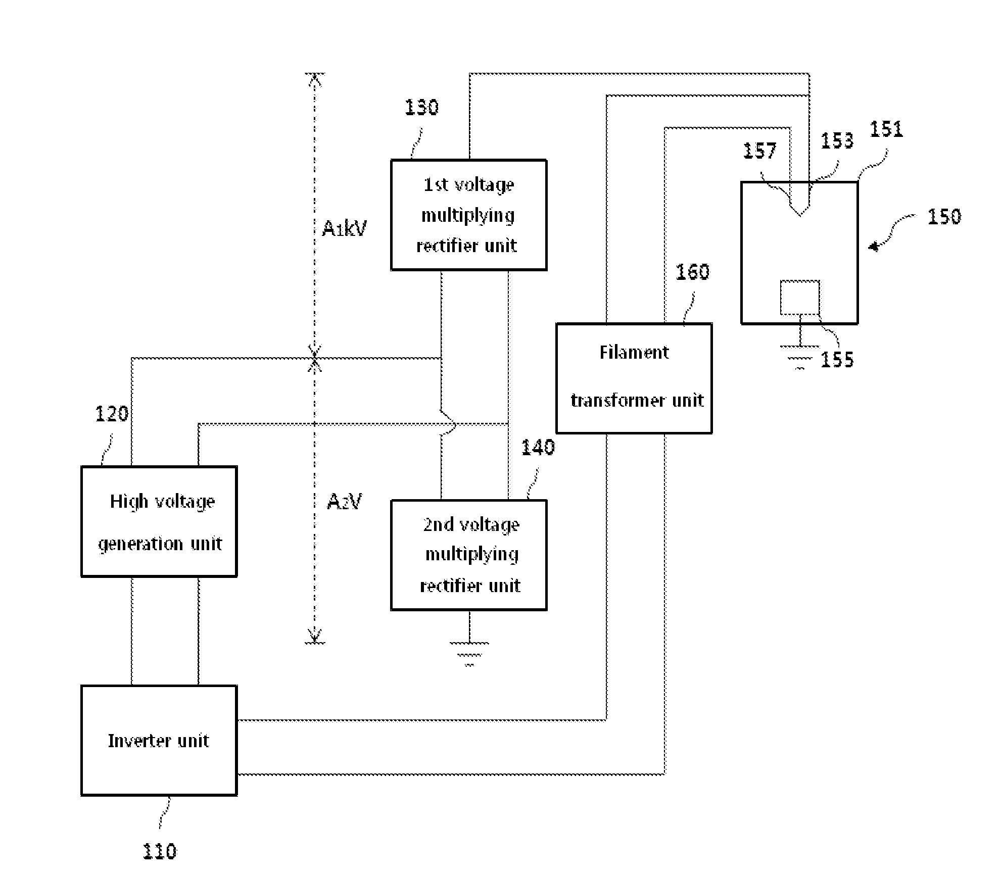
[0041]Hereinafter, a high voltage driving device for X-ray tube according to the present invention will be described in more detail with reference to the accompanying drawings.

[0042]FIG. 3 is a functional block diagram illustrating the inner configuration of a high voltage driving device for X-ray tube according to the present invention.

[0043]Referring to FIG. 3, an inverter unit 110 receives a supply of a commercial AC power and converts the received commercial AC power into a high-frequency AC power through a high-speed switching operation. A high voltage generation unit 120 receives a supply of the high-frequency AC power from the inverter unit 110 to generate a high-voltage power. A first voltage multiplying rectifier unit 130 and a second voltage multiplying rectifier unit 140 are in series connected to each other based on the high voltage generation unit 120. The first voltage multiplying rectifier unit 130 receives a supply of the high-voltage power generated from the high vo...


PUM


Abstract

The present invention relate to an X-ray photographing apparatus, and more particularly, to a high voltage driving circuit for X-ray tube, in which a first voltage multiplying rectifier unit and a second voltage multiplying rectifier unit are in series connected to each other based on a high voltage generation unit to stably convert a high voltage power generated from the high voltage generation unit into a drive power for an X-ray tube with high energy efficiency, and in which a plurality of isolation transformers or high voltage transformers is in series connected to each other in the high voltage generation unit to divide a voltage of the second voltage multiplying rectifier unit into a withstanding voltage of the isolation transformers or the high voltage transformers, thereby ensuring excellent insulation properties.

Description

CROSS-REFERENCE TO RELATED APPLICATIONS[0001]This application claims the benefit of Korean Patent Application No. 10-2012-0098412, filed on Sep. 5, 2012 in the Korean Intellectual Property Office, which is incorporated herein by reference in its entirety.BACKGROUND OF THE INVENTION[0002]1. Field of the Invention[0003]Exemplary embodiments of the present invention relate to an X-ray photographing apparatus, and more particularly, to a high voltage driving circuit for X-ray tube, in which a first voltage multiplying rectifier unit and a second voltage multiplying rectifier unit are in series connected to each other based on a high voltage generation unit to stably convert a high voltage power generated from the high voltage generation unit into a drive power for an X-ray tube with high energy efficiency, and in which a plurality of isolation transformers or high voltage transformers is in series connected to each other in the high voltage generation unit to divide a voltage of the sec...

Claims


Application Information

Patent Timeline
IPC IPC(8): H05G1/12
CPCH05G1/12H05G1/20H01J35/02H05G1/10H02M7/10
Inventor PARK, JONG LAESUNG, KI BONG
Owner POSKOM CO LTD
Why Eureka
Try Eureka