Pump

a rotary pump and rotary pump technology, applied in the direction of piston pumps, positive displacement liquid engines, liquid fuel engines, etc., can solve the problems of non-uniform sum of instantaneous flow rates that are pumped by the pump, non-uniform speed of fluid flow, and non-uniform flow rate of fluid that is forcibly delivered, so as to reduce the length of the route, prevent surging, and improve the structure of the power transmission system of the transmission uni

Inactive Publication Date: 2013-01-31
PHILTEC CO LTD
View PDF5 Cites 0 Cited by
  • Summary
  • Abstract
  • Description
  • Claims
  • Application Information

AI Technical Summary

Benefits of technology

[0017]In an aspect of the present invention, provided is a double action rotary pump, which is intended to forcibly deliver fluid such as liquid or gas. The pump includes a transmission unit and an operating unit provided in series with the transmission unit. The transmission unit operates at uniform or non-uniform angular speeds using driving force that is transmitted from a motor via a power transmission system, which includes a combination of concentric and eccentric gears. In the operating unit, a piston has a pair of heads, which rotate at non-uniform angular speeds in a counteracting fashion while maintaining the distance between shafts, and divides the spaces inside cylinders. The volumes of the divided spaces of the cylinders are repeatedly and alternately contracted and expanded in response to the rotation of the piston, so that the cylinders counteractively and continuously perform intake and exhaust operations, thereby forcibly delivering fluid. The structure of the power transmission system of the transmission unit is improved such that the sum of flow rates that are pumped by the piston at a predetermined time point stays uniform. Accordingly, a fixed amount of fluid can be forcibly delivered, thereby making it possible to prevent surging. In addition, it is possible to decrease the length of the route along which power is transmitted and reduce the number of the stages of the power transmission system by simplifying the structure, thereby reducing mechanical friction or load. Accordingly, it is possible to increase the operating efficiency of the pump and improve the quality of the pump.
[0018]According to embodiments of the invention, the driving force is distributed using the distribution stage and the delivery stage of the power transmission system, which is realized by combining concentric and eccentric gears, so that the first and second shafts operate in counteractive non-uniform angular speeds. Consequently, the sum of flow rates that are pumped by the piston at a predetermined time point can stay uniform, thereby enabling a fixed amount of fluid to be forcibly delivered, preventing surging. Accordingly, it is possible to remove noises or vibration, thereby improving the endurance of devices and improving the performance of the pump.
[0019]In addition, according to embodiments of the invention, it is possible to precisely measure a flow rate and forcibly deliver a fixed amount of fluid by maintaining the amount of fluid that is pumped by the pump to be uniform, thereby enabling high-precision control over forced delivery.
[0020]Furthermore, according to embodiments of the invention, the first and second shafts of the transmission unit operate at non-uniform angular speeds using the power transmission system, which is realized by combining the worm, which moves like a pendulum, and the pair of eccentric worm gears, which are provided on both sides of the worm such that the worm is disposed in the middle between them. Accordingly, it is possible to simplify the structure, reduce the number of parts, and simplify the parts, thereby reducing the cost of manufacture.
[0021]In addition, according to embodiments of the invention, the power transmission system is realized by combining a minimum number of mechanical elements such that the length of the route along which power is transmitted and the stages of the power transmission system are decreased, thereby reducing mechanical friction and load. Accordingly, it is possible to reduce power consumption, increase the efficiency of operation, and improve the quality of the pump.
[0022]Furthermore, according to embodiments of the invention, since the amount of fluid that is pumped by the pump is maintained uniform, it is possible to precisely measure a flow rate and forcibly deliver a fixed amount of fluid, thereby enabling high-precision control over forced delivery.

Problems solved by technology

However, in the pump configured as above, variable long and short distances between the shafts are mutually corrected due to the operation at uniform and non-uniform angular speeds, so that an intended pumping operation is enabled.
However, in the operation of this type of pump, one of the first and second shafts operates at non-uniform speeds.
Due to the non-uniform angular operation that is intended to correct the distance between the shafts, the flow rate of fluid that is forcibly delivered is non-uniform, which is attributable to changes in the angular speed due to the maximum and minimum diameter portions between the eccentric gears.
Consequently, the sum of the instantaneous flow rates that are pumped by the pump is not uniform.
Therefore, the non-uniformity of the flow rate of fluid that is pumped is a main reason for surging that would cause a problem in the operation of the pump.
The surging of the pump causes a number of problems, which degrade the quality of the pump.
Specifically, the surging creates noises and vibration, decreases the lifespan of devices, decreases the efficiency of the pump, and disables high-precision control over forced delivery, such as delivery at a fixed amount.
Therefore, the spatial arrangement of the power transmission system is difficult.
The configuration is complicated since several types of gears having large and small diameters are systematically and continuously associated with adjacent elements.
Consequently, there are problems in that is difficult to fabricate the pump and that the cost of manufacture of the pump increases.
Furthermore, since the power transmission system is composed of several stages, the distance of a power transmission route unnecessarily extends, thereby increasing the distance between an input and an output of driving force.
In addition, mechanical friction or load between mechanical elements in respective stages increases power loss, so that power that is consumed in the operation of the pump increases, thereby decreasing the operating efficiency of the pump.

Method used


Image

  • Pump
  • Pump
  • Pump

Examples


Embodiment Construction

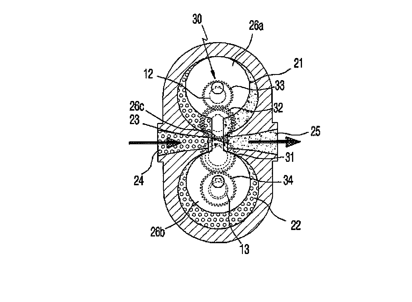
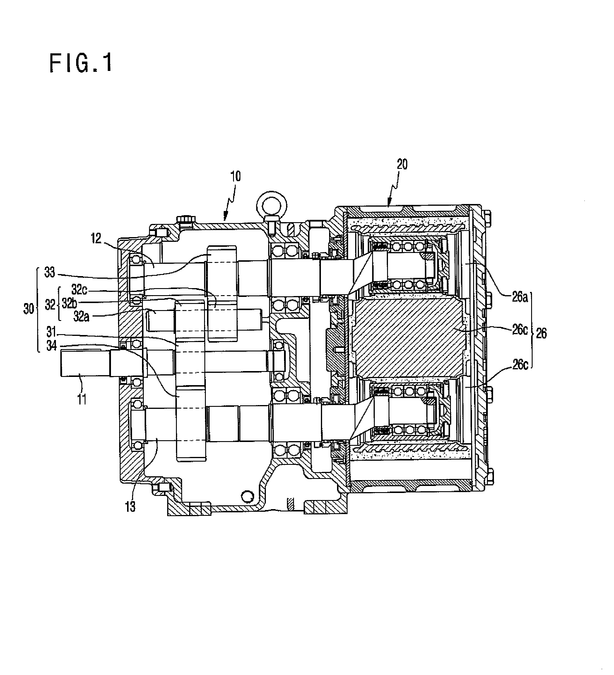
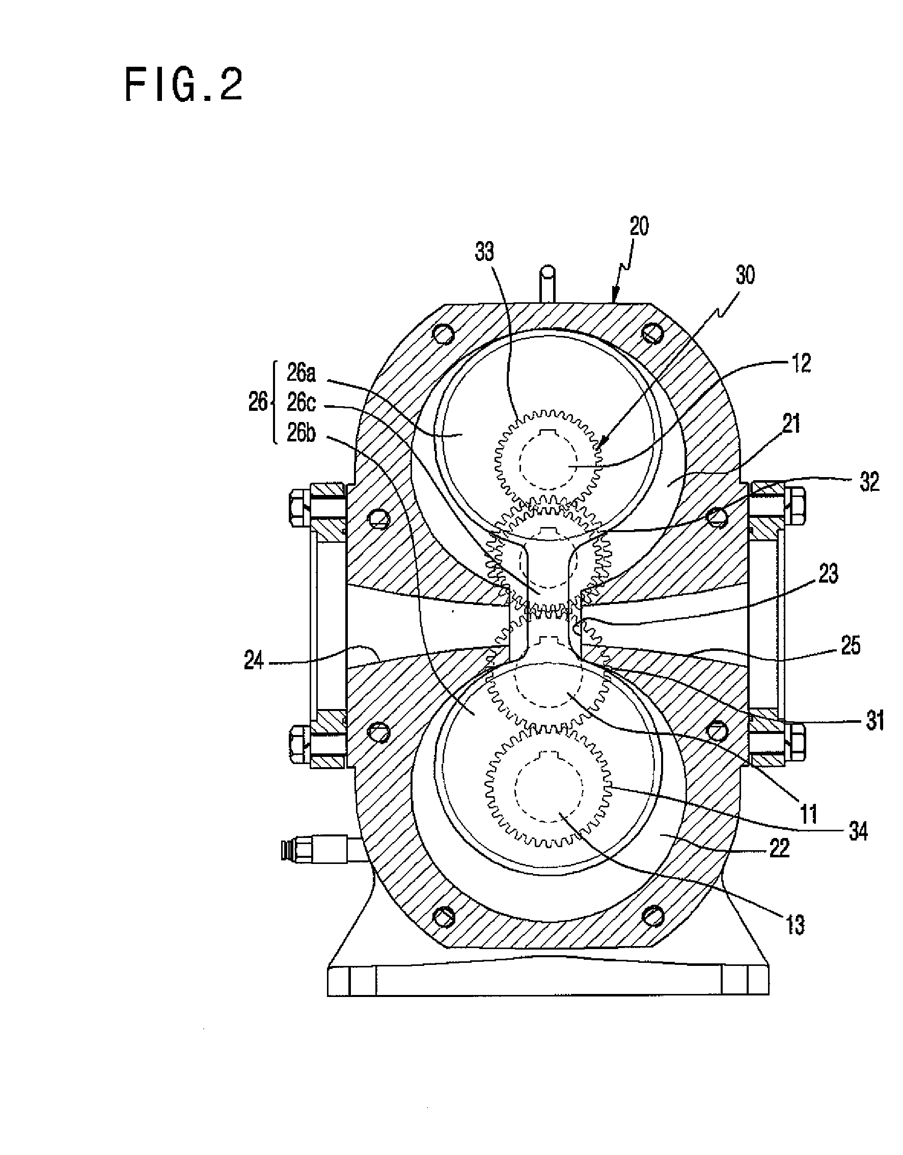
[0034]Reference will now be made in detail to various embodiments of the present invention, examples of which are illustrated in the accompanying drawings and described below. FIG. 1 and FIG. 2 show a pump according to an embodiment of the invention in detail. The invention provides a double action rotary pump, which is intended to forcibly deliver fluid such as liquid or gas.

[0035]The pump of this embodiment generally includes a transmission unit 10 and an operating unit 20, which are surrounded by respective casings such that they are isolated from each other.

[0036]First, the transmission unit 10 includes a main drive shaft 11 in the central portion of the body thereof, the main drive shaft 11 receiving driving force from a motor or the outside, a pair of crank-type first and second shafts 12 and 13, which are arranged in parallel in the upper and lower positions. The first and second shafts 12 and 13 are associated with the main drive shaft 11 and follow it via a power transmissi...


PUM


Abstract

A double action rotary pump forcibly delivers fluid such as liquid or gas. A transmission unit operates at uniform or non-uniform angular speeds using driving force transmitted from a motor via a power transmission system. An operating unit is provided in series with the transmission unit. A piston of the operating unit has a pair of heads, which rotate at non-uniform angular speeds in a counteracting fashion while maintaining the distance between shafts, and divides the spaces inside cylinders. The volumes of the divided spaces of the cylinders are repeatedly and alternately contracted and expanded in response to the rotation of the piston, so that the cylinders counteractively and continuously perform intake and exhaust operations, thereby forcibly delivering fluid. The structure of the power transmission system is improved such that the sum of flow rates that are pumped by the piston at a predetermined time point stays uniform.

Description

CROSS REFERENCE TO RELATED APPLICATION[0001]The present application claims priority from Korean Patent Application Numbers 10-2011-75023 filed on Jul. 28, 2011 and 10-2012-26107 filed on Mar. 14, 2012, the entire contents of which application are incorporated herein for all purposes by this reference.BACKGROUND OF THE INVENTION[0002]1. Field of the Invention[0003]The present invention relates to a double action rotary pump, which is intended to forcibly deliver fluid such as liquid or gas. More particularly, the present invention relates to a pump, in which spaces of cylinders are divided by a piston that has a pair of heads, each of which is provided inside a corresponding cylinder so as to be eccentric from the center of the cylinder such that each head rotates inside the cylinder. In this pump, the volumes of the divided spaces of the cylinders are repeatedly and alternately contracted and expanded in response to the rotation of the heads so that intake and exhaust operations of ...

Claims


Application Information

Patent Timeline
Patent Type & Authority Applications(United States)
IPC IPC(8): F01C17/02F04C2/00F04C23/00
CPCF04B9/02F04C11/001F04C2/06F04C29/0042
Inventor RHA, PHIL CHAN
Owner PHILTEC CO LTD
Why Eureka
Try Eureka