Vehicle headlight

a headlight and vehicle technology, applied in vehicle headlights, transportation and packaging, lighting and heating apparatus, etc., can solve the problems of headlight using lighting units that do not conform to light distribution standards, experience decreased visibility, debasement or devaluation of merchantability, etc., to improve light use efficiency, improve faraway or distance visibility, and high efficiency

Inactive Publication Date: 2010-12-09
STANLEY ELECTRIC CO LTD
View PDF4 Cites 43 Cited by
  • Summary
  • Abstract
  • Description
  • Claims
  • Application Information

AI Technical Summary

Benefits of technology

[0023]Therefore, the projector headlight can exhibit improved faraway or distance visibility because light emitted from the LED light source can illuminate at a faraway point. Furthermore, each of the second focuses of the other ellipsoidal reflectors other than at least the ellipsoidal reflector can also be located substantially on the first top edge line of the shade and the second top edge line in order to improve light use efficiency. Thus, the disclosed subject matter can provide a small projector headlight that can perform a favorable light distribution pattern with a high efficiency and low power consumption, and which can be used for various types of vehicles, including electrical cars and the like.

Problems solved by technology

If each variation of the light distribution patterns becomes large, their variations may cause a problem such that a headlight using the lighting units does not conform to a light distribution standard for a headlight.
However, the vehicle headlight may experience decreased visibility and therefore may have a debasement or devaluation of merchantability.

Method used


Image

  • Vehicle headlight
  • Vehicle headlight
  • Vehicle headlight

Examples


Embodiment Construction

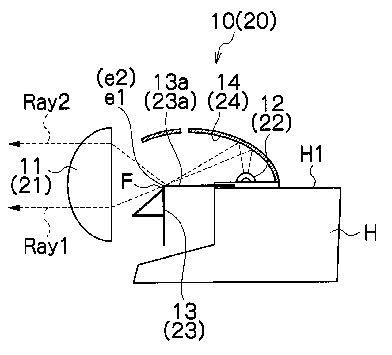
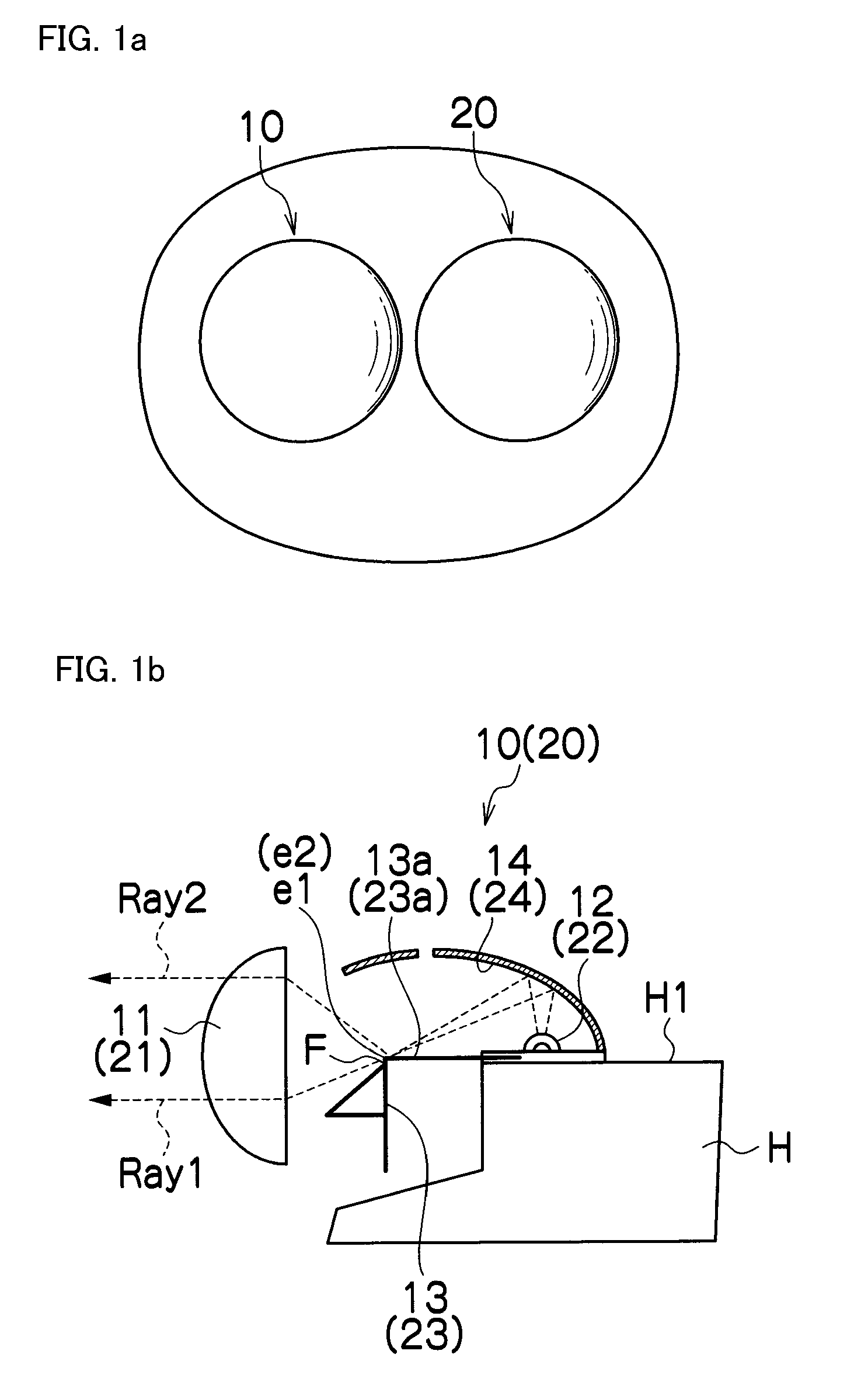
[0032]The disclosed subject matter will now be described in detail with reference to FIG. 1 to FIG. 6. FIG. 1a is a top view showing an exemplary vehicle headlight for a low beam made in accordance with principles of the disclosed subject matter, and FIG. 1b is a schematic side cross-section view showing an exemplary structure of a first and second lighting unit included in the exemplary vehicle headlight.

[0033]The exemplary vehicle headlight of FIG. 1a can include a first lighting unit 10 and second lighting unit 20 that can form a light distribution pattern P for a low beam as described later. The first lighting unit 10 can include: a projector lens 11 located in a forward direction of the vehicle headlight; an LED light source 12 located in a rearward direction of the vehicle headlight; a shade 13 located between the projector lens 11 and the LED light source 12; and a reflector 14 located in a light-emitting direction of the LED light source 12.

[0034]The projector lens 11 can ha...


PUM


Abstract

A projector headlight for a low beam can include a first and second lighting unit. Each of the first and second lighting units can include an LED light source, an ellipsoidal reflector, a projector lens and a shade. Light emitted from the LED light source can form a light distribution pattern from the projector lens via the ellipsoidal reflector by shielding an upwards portion of the light with the shade. The shade of the second lighting unit may be configured so as not to project light on a specific point under a cut-off line on an oncoming lane using a convex portion thereon. Therefore, the first lighting unit can project light with a maximum light intensity at the specific point so as to overlap the light distribution pattern formed by the second lighting unit. Thus, the projector headlight can perform a favorable light distribution pattern that can conform to a light distribution standard for headlights.

Description

[0001]This application claims the priority benefit under 35 U.S.C. §119 of Japanese Patent Application No. 2009-135506 filed on Jun. 4, 2009, which is hereby incorporated in its entirety by reference.BACKGROUND[0002]1. Field[0003]The presently disclosed subject matter relates to a vehicle headlight of a projector type, and more particularly to a projector headlight including a plurality of lighting units for a low beam that can form a favorable light distribution pattern, and which can conform to a light distribution standard for a headlight.[0004]2. Description of the Related Art[0005]An LED has been used as a light source for a vehicle headlight, and a plurality of lighting units using the LED light source are frequently incorporated into the vehicle headlight such as a projector headlight and the like. The projector headlight may allow a light-emitting area thereof to be reduced and therefore allows the headlight to be minimized in comparison with other type headlights. In additi...

Claims


Application Information

Patent Timeline
Patent Type & Authority Applications(United States)
IPC IPC(8): B60Q1/04
CPCF21S48/1159F21S48/145F21S48/1388F21S41/148F21S41/255F21S41/321F21S41/365F21S41/43
Inventor YAMAGATA, SHINJIAKUTAGAWA, TAKASHI
Owner STANLEY ELECTRIC CO LTD
Why Eureka
Try Eureka