

Switchable Attenuation Circuit for MEMS Microphone Systems
a technology of attenuation circuit and microphone, which is applied in the direction of frequency response correction, transducer type, and electrostatic transducer of semiconductor, can solve the problems of loss of signal contents, circuitry may not be able to handle, and undesirable distortion, so as to avoid or reduce clipping
- Summary
- Abstract
- Description
- Claims
- Application Information
AI Technical Summary
Benefits of technology
Problems solved by technology
Method used
Image

Examples
Embodiment Construction
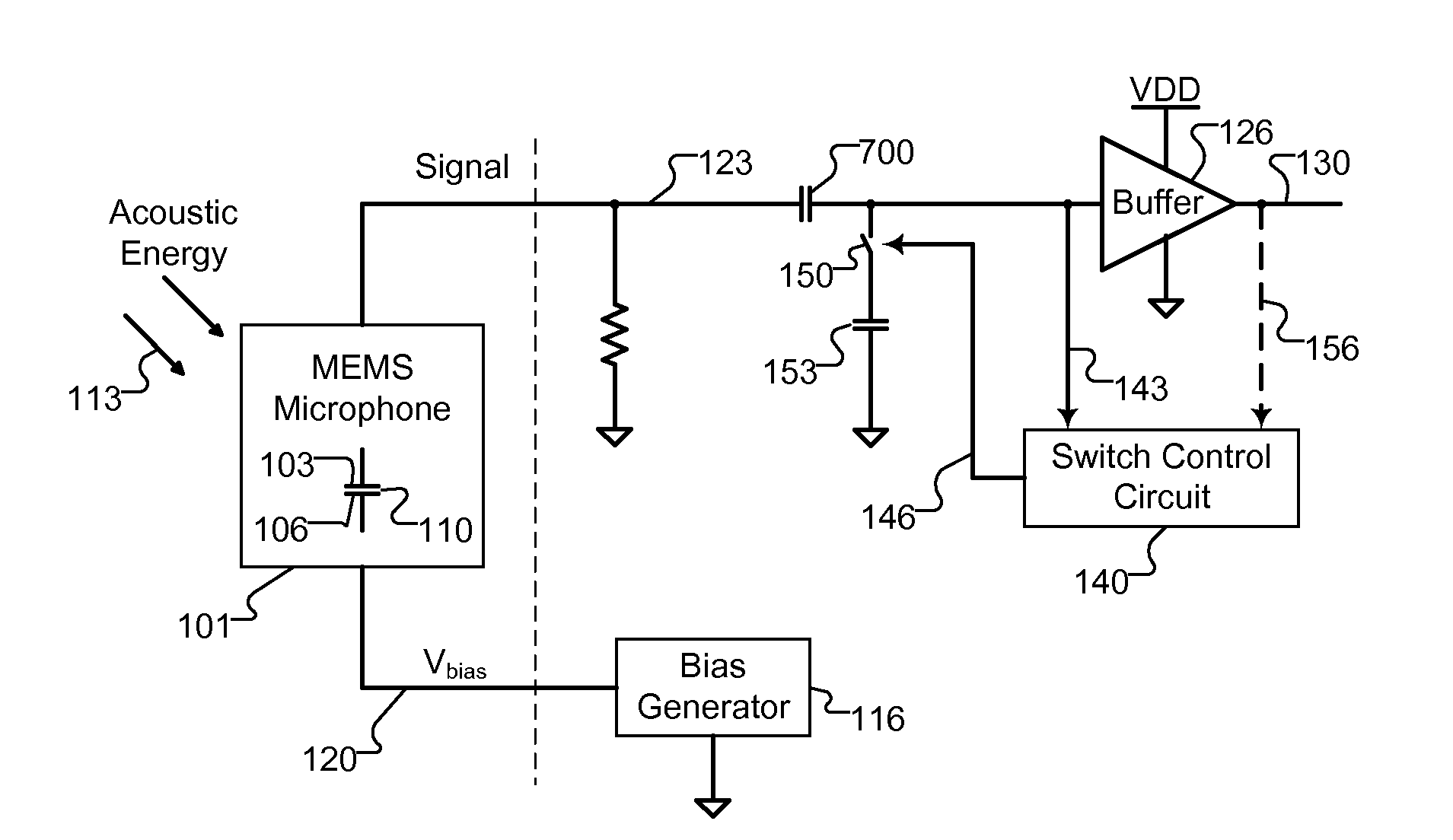
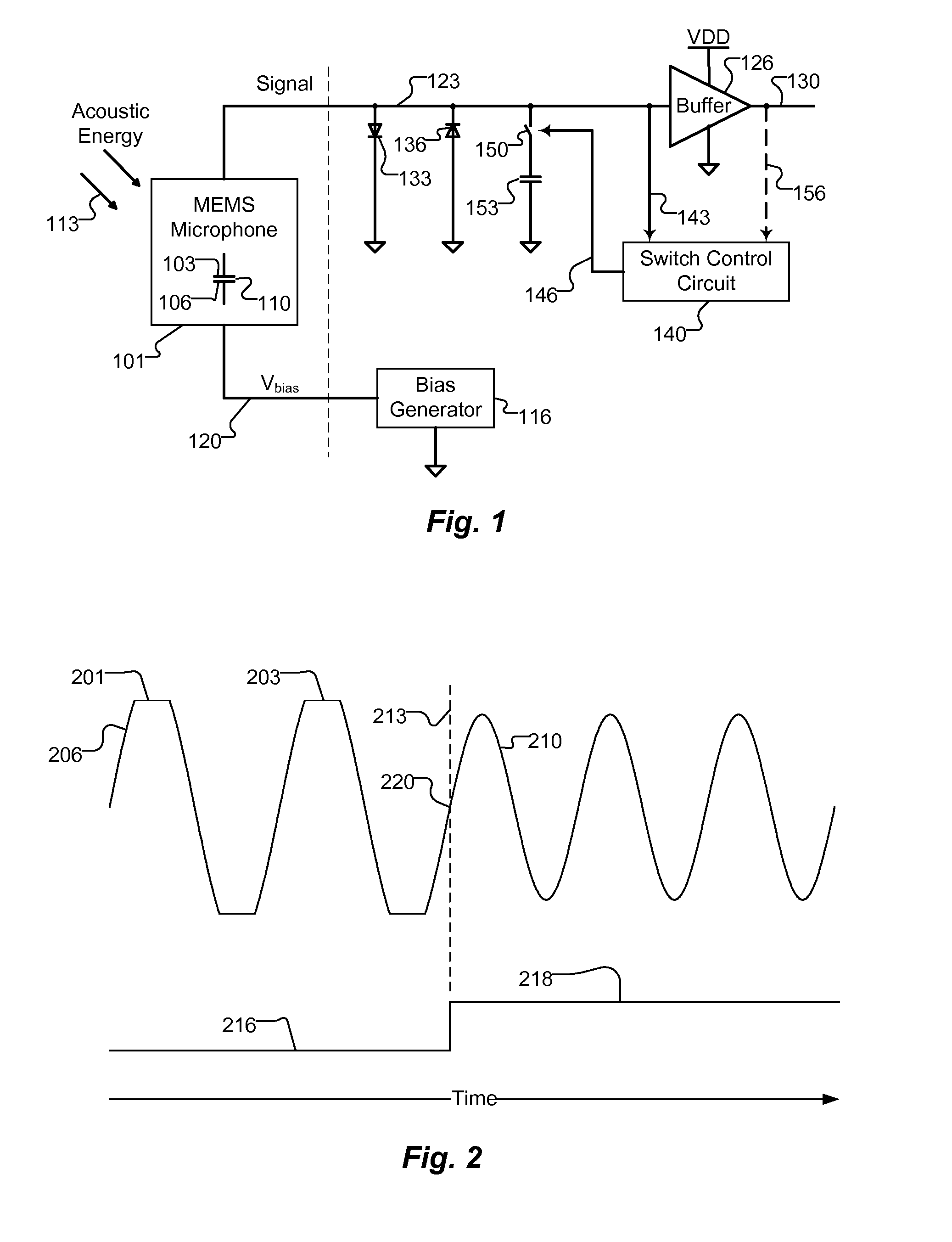
[0006]An embodiment of the present invention provides a microphone system configured to avoid or reduce clipping. The microphone system includes a movable structure and an electrode, such as a MEMS or other capacitor microphone. The movable structure is movable in response to an acoustic signal. The movable structure and the electrode establish a capacitance that varies with the acoustic signal to which the moveable structure is subjected. Movement of the moveable structure produces an electrical signal. The microphone system also includes a circuit for processing the signal. A switch selectively operates to connect a capacitance to a conductive line carrying the signal, so as to attenuate the signal before it is processed by the circuit.
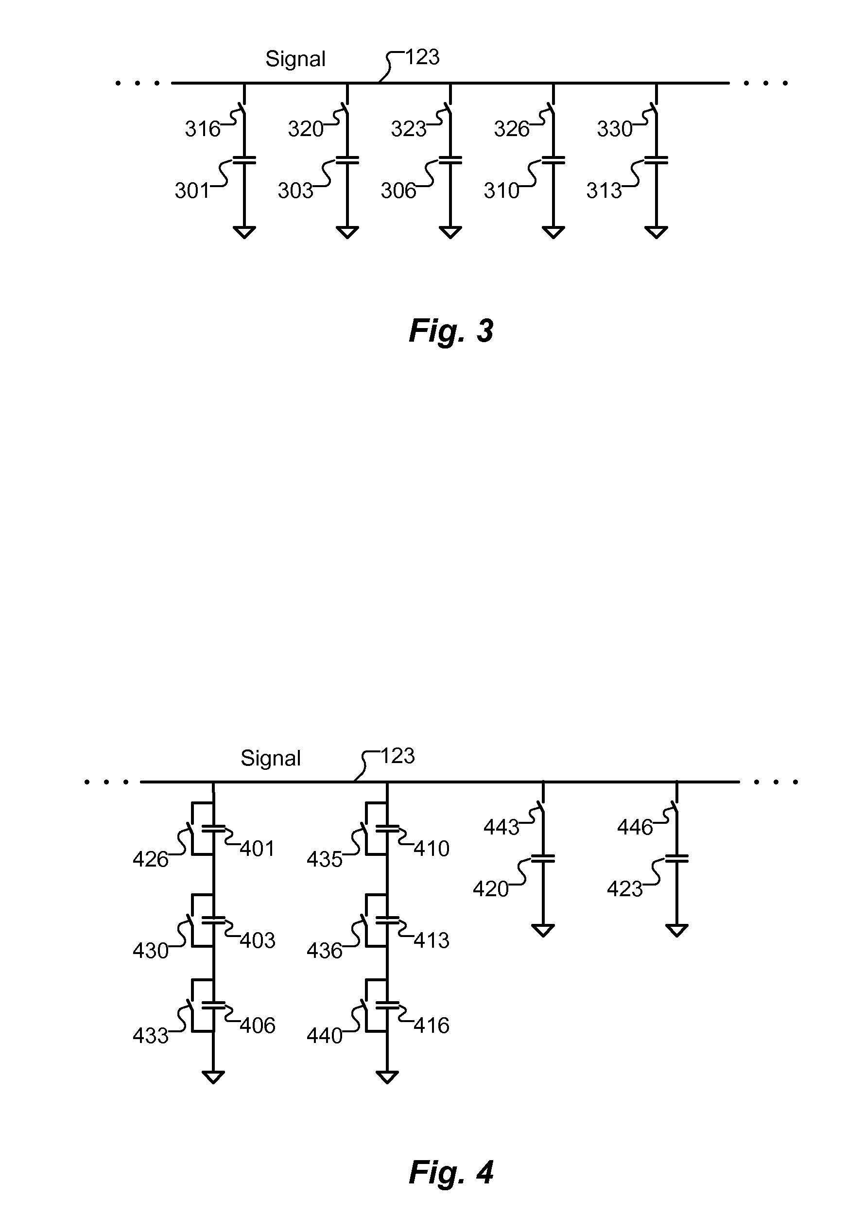
[0007]The capacitance may include one or more capacitors connected to the switch. Each capacitor may have a different capacitance.
[0008]The switch may include a plurality of switches connected to the plurality of capacitors, such that the capacitanc...
PUM
 Abstract
Description
Claims
Application Information