System and method for avoiding clipping in a communications system

a communication system and clipping technology, applied in the field of clipping avoidance, can solve the problems of loss of data at the establishment of the call or call segment, delay in establishing the packet stream for audio data and other real-time media data, and inconvenient audio data, so as to reduce the size of the buffer

Inactive Publication Date: 2006-07-13
SIEMENS ENTERPRISE COMM GMBH & CO KG
View PDF12 Cites 61 Cited by
  • Summary
  • Abstract
  • Description
  • Claims
  • Application Information

AI Technical Summary

Benefits of technology

[0015] It is an object of the invention to provide a system and method that utilizes a buffer to store packets and subsequently reduces the size of the buffer at a time when at least some of the packets in the buffer can be rendered.

Problems solved by technology

When establishing a telephone or multi-media call over a packet network such as a network using the Internet Protocol (IP), there can be a delay in establishing the packet streams for audio data and other real-time media data.
This can lead to the loss of data at the establishment of the call or call segment.
This can be particularly apparent and inconvenient for audio data in the direction called party to calling party (backward direction), since the initial greeting can be wholly or partially lost.
Unfortunately there are several reasons why transmitting packets or receiving and rendering packets cannot happen immediately.
However, the underlying reasons cannot be solved by choice of signalling protocol.
The reasons listed below apply to delays in establishing the backward audio stream, but similar considerations can lead to delays in establishing the forward audio stream and likewise streams for other media.
On the other hand, audio packets typically take a direct route from the called device to the calling device to avoid any unwanted delay, which can have a negative impact on the quality of the conversation.
The answer signal may contain information needed by the calling device to identify the backward stream of audio packets, and the calling device may be unable or unwilling (for security reasons) to accept and render received audio packets until the answer message arrives.
However, if answer occurs at one of the other forked-to destinations (whether or not that destination is reached via a gateway), delays in receiving the answer signal and switching to the appropriate backward audio stream can cause loss of important audio data.
Another scenario usually affects a transmitting device, wherein the transmitting device, e.g., a called device, may not have sufficient information at the time of answer to start transmitting audio packets to the calling device.
The result is the loss of audio data until the called device has obtained the necessary information.
There can be situations where a real-time medium (e.g., audio) can be transmitted over an Internet Protocol (IP) network via an intermediate entity, which introduces delays due to coding / decoding, packetisation and jitter absorption as well as any internal processing.
This is often unavoidable because of the value added by the intermediate entities (eg., conference bridging, transcoding).
Although in some cases it may be possible to do this before the call is answered, in other situations (e.g., where the call is broadcast to a number of endpoints, any one of which can answer), rerouting is not possible until after answer.
Unfortunately the process of rerouting real-time media streams during a call can introduce some discontinuity in the real-time media received at each endpoint.
Simply discarding any outstanding packets on the old path will lead to a discontinuity in the form of lost audio samples, perhaps resulting in the loss of entire syllables or words.
The alternative of discarding packets on the new path until all packets on the old path have been received will likewise lead to lost audio samples, and this technique also introduces the problem of detecting when the last packet has been received on the old path.
Yet another solution is to play all packets received on the old stream and buffer packets received on the new stream for play later, but as presently implemented this technique just maintains the delay inherent in the old path and fails to exploit the reduced delay on the new path.

Method used


Image

  • System and method for avoiding clipping in a communications system
  • System and method for avoiding clipping in a communications system

Examples


Embodiment Construction

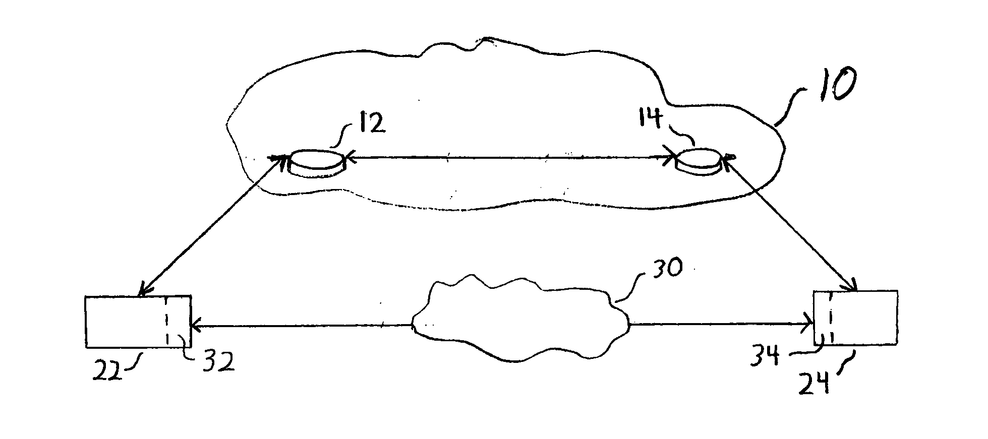
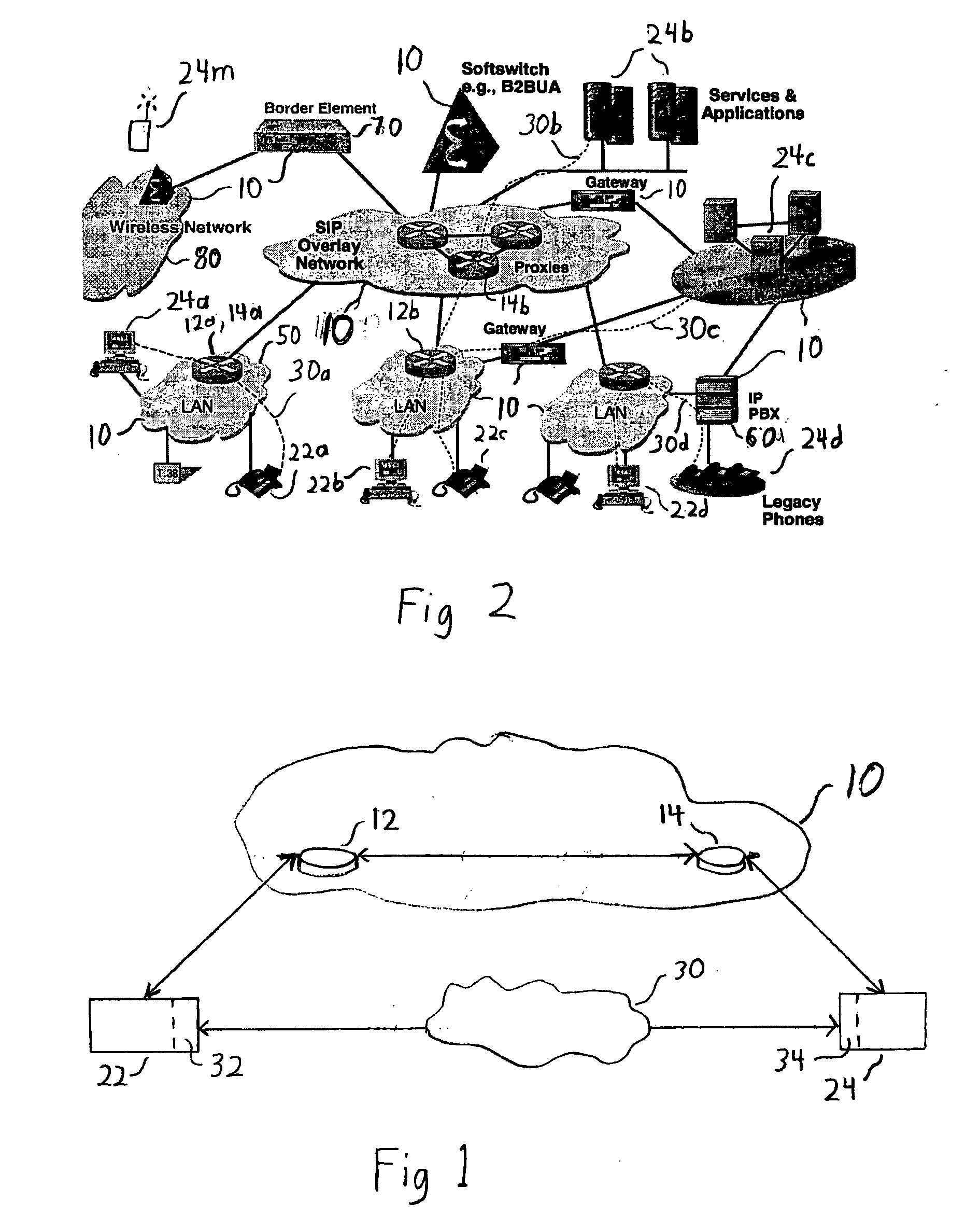
[0026] With reference to FIG. 1, signalling network 10 is shown. In a preferred embodiment, signalling network 10 comprises signalling proxy 12 and signalling proxy 14.

[0027] Calling device 22, which may be, for example, a voice over IP (VoIP) telephone, is used by a first user wishing to make a call to a second user at called device 24, which may be, for example, another VoIP telephone. The first user provides calling device 22 with information to reach the second user at device 24, for example a telephone number. Calling device 22 alerts signalling proxy 12, which sends a signal to signalling proxy 14. Signalling proxy 14 causes an alert (e.g., a ringing tone) to emit from called device 24. The second user picks up (e.g. picks up a handset at called device 24) and starts speaking.

[0028] In a first scenario, called device 24 has enough information to start sending data packets, which for the purpose of illustration is audio packets, through packet network 30. In a preferred embod...


PUM


Abstract

In a communication system, a buffer is provided at or between a transmitting device and a receiving device. When the transmitting device is unable to send a stream of media packets or the receiving device is unable to render the stream of media packets, the buffer stores the media packets, and the size of the buffer is reduced when the transmitting device is able to send the stream of media packets and/or the receiving device is able to render the stream of packets.

Description

CROSS-REFERENCE TO RELATED APPLICATION [0001] This application claims priority to Great Britain Patent Application 0500606.9 entitled “Method of Eliminating Real-Time Data Loss on Establishing a Call” filed on Jan. 13, 2005. BACKGROUND OF THE INVENTION [0002] 1. Field of the Invention [0003] The present invention relates to clipping avoidance in a communications environment. More particularly, the present invention relates to utilizing a buffer to store packets of data so that the data may be rendered at a slightly later time e.g., when the user media stream is completely established. 2. Description of the Related Art [0004] When establishing a telephone or multi-media call over a packet network such as a network using the Internet Protocol (IP), there can be a delay in establishing the packet streams for audio data and other real-time media data. This can lead to the loss of data at the establishment of the call or call segment. This can be particularly apparent and inconvenient fo...

Claims


Application Information

Patent Timeline
Patent Type & Authority Applications(United States)
IPC IPC(8): H04J3/06H04J3/16H04J3/22H04L12/66H04L12/56H04L29/06
CPCH04J3/0632H04L29/06027H04L47/10H04L47/18H04L47/2416H04L47/283H04L47/32H04L65/4092H04L65/613H04L65/1101
Inventor STUMER, PEGGY MARIE
Owner SIEMENS ENTERPRISE COMM GMBH & CO KG
Why Eureka
Try Eureka