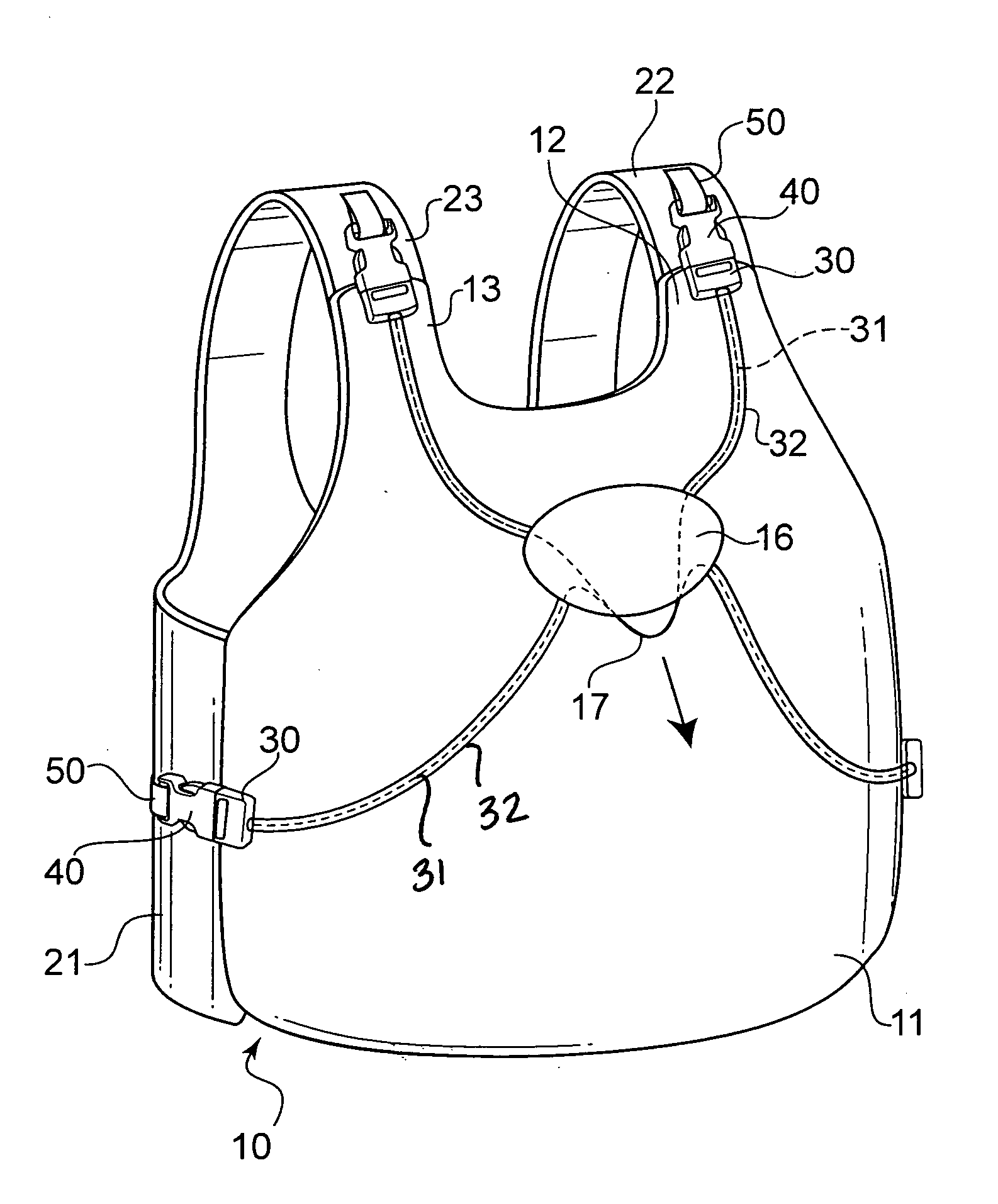
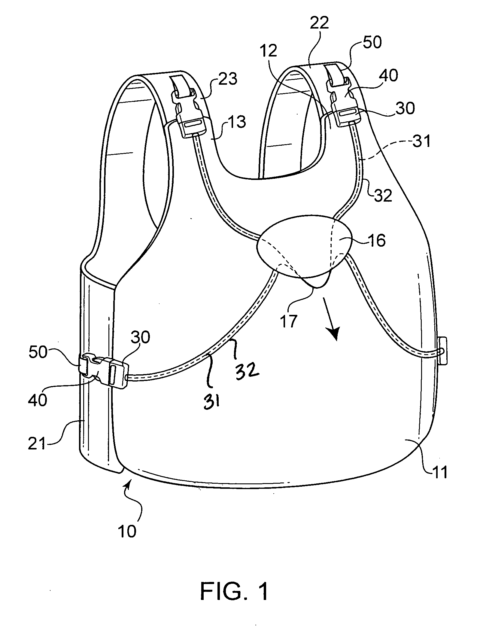
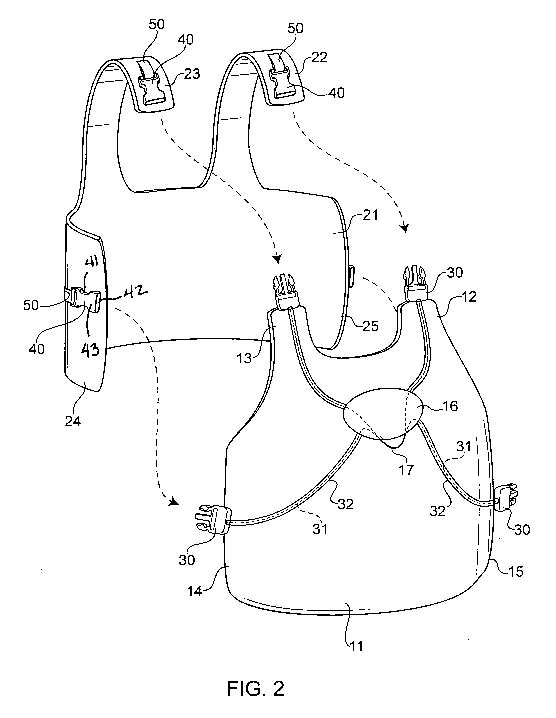
[0028]Referring now in detail to the drawings, FIGS. 1 and 2 show a vest 10 according to one embodiment of the invention. Vest 10 consists of a front vest piece 11 connected to a rear vest piece 21. Front vest piece 11 has two shoulder sections 12, 13 and two waist sections 14, 15. Rear vest piece has two shoulder sections 22, 23 and two waist sections 24, 25. Rear vest piece 21 is connected to front vest piece 11 via buckles located on each of shoulder sections 12, 13, 22, 23 and waist section 14, 15, 24, 25. Front vest piece 11 is equipped with male buckle portions 30 on each of sections 12, 13, 14, 15, and rear vest piece 21 is equipped with female buckle portions 40 attached to sections 22, 23, 24, 25. Male buckle portions 30 on front vest piece 11 are releasably connected to corresponding female buckle portions on rear vest piece 21 to connect the two vest pieces together.
[0029]Because vest pieces 11, 21 must be connected while vest 10 is being worn, it is ideal if rear waist sections 24, 25 are reinforced with a stiff, curved material, so that rear vest piece 21 will stay in place prior to attachment of front sections 14, 15 of front vest piece 11. Preferably, waist sections 25, 24, extend around toward the front of the user, so that there is a significant overlap between waist sections 15, 14 and 25, 24. To put on the vest, the shoulder sections of front vest piece 11 are connected to the shoulder sections of rear vest piece 21 and the vest 10 is placed over the wearer's head. The waist sections 15, 14, are then connected to waist sections 25, 24, respectively, to secure vest 10 to the wearer. The vest can be adjusted by adjusting straps 50 which are connected to female buckle portions 40, to increase the comfort and safety of the wearer. Or, the rear vest piece 21 can be placed on the wearer's body, and the front vest piece 11 can be connected to it while on the wearer, with the buckles being connected in any order.
[0030]So that vest 10 can be easily removed in an emergency, front vest piece 11 is constructed so that male buckle portions 30 can be released from female buckle portions 40 with one movement. In this embodiment, each male buckle portion 30 is connected to a cable 31, which is attached to a handle 17 on front vest piece 11. Cable 31 is fed through a cable sleeve 32, which is secured to front vest piece 11, and through which cable can easily slide. In the embodiment of FIGS. 1 and 2, cables on the left side of the vest are connected to each other prior to connection to handle 17. The same is true for the right side cables. Handle 17 and cables 31 are secured in place on front vest piece 11 by a patch 16, which guide the cables where the handle is interconnected.
[0031]Male buckle portions 30 are configured so that a hard pull on handle 17 causes all four buckle portions 30 to simultaneously disengage from the corresponding female portions 40, thus separating front vest piece 11 from rear vest piece 21 with a single motion. Because there are only two pieces to vest 10, and only four buckles, re-assembling vest 10 is simple and quick. All that is required is to insert male buckle portions 30 back into female buckle portions 40, and the vest is completely assembled, ready for another use.
[0032]The cables 31 that are connected to the male buckle portions 30 on front sections 12, 13 and 14, 15 are. interconnected to handle 17. This is to allow a downward pull on handle 17 to move the cable sufficiently to disengage male buckle portions 30 on the waist sections.
[0033]FIGS. 3 and 4 show one embodiment of a male buckle portion that is suitable for use in vest 10. Female buckle portion is a conventional female buckle portion, having a hollow body 43, a central opening 42 and two locking slots 41, as shown in FIG. 2. Male buckle portion 30 comprises a base 33, two flexible locking legs 34 and a central leg 35 with a guide channel. Within the guide channel of central leg 35 is a slidable pulling mechanism 36. Connected to mechanism 36 and to locking legs 34 are two pulling arms 37. Also connected to mechanism 36 is cable 31. In use, pulling on cable 31 causes pulling mechanism 36 to slide back away from locking legs 34. This pulls arms 37 downward, and pulls locking legs 34 inward, as shown in FIG. 4. This inward motion of locking legs 34 causes male buckle portion 30 to release from female buckle portion 40 when the two buckle portions are assembled together.
[0034]FIGS. 5 and 6 show an alternative embodiment of male buckle portion 30. In this embodiment, cable 31 is connected to a Y-shaped pulling mechanism 336. This can be a hollow structure through which cable 31 is threaded and splits into arms 337, which are connected to locking legs 34 through aperture 339 and knob 338. Alternatively, cable 31 can be attached to an end of mechanism 336, with arms 337 attached to the two Y-arms of. mechanism 336. As with the embodiment of FIGS. 3 and 4, pulling on cable 31 causes pulling mechanism 336 to slide back away from locking legs 34. This causes arms 337 to pull locking legs 34 inward, as shown in FIG. 6. The inward motion of locking legs 34 causes locking legs 34 to be released from locking slots 41 in female buckle portion 40, to release male buckle portion 30 from female buckle portion 40.
[0035]FIGS. 7 and 8 show another embodiment of male buckle portion 30. In this embodiment, a connecting strap 437 extends between locking legs 34. A pulling mechanism 436 is slidably disposed in central leg 35 and is attached to a center of connecting strap 437. As shown in FIG. 8, when cable 31 is pulled, pulling mechanism 436 pulls strap 437 downward and causes locking legs 34 to be pressed inward, to release locking legs 34 from female portion 40.
[0036]FIGS. 9 and 10 show yet another embodiment of male buckle portion 30. In this embodiment, a hollow receptacle 538 is integrally molded into straps 537, which connect locking legs 34 to each other. Within hollow receptacle 538 is a pulling mechanism 536, which is connected to cable 31. Pulling on cable 31 pulls straps 537 downward and causes locking legs 34 to be pressed inward, as shown in FIG. 10. This allows male buckle portion 30 to be released from female buckle portion 40.
[0037]Other buckle assemblies could also be envisioned. All that is required is that the male portions be releasable from the female portions by pulling on the handle or cable.
[0038]Accordingly, while only a few embodiments of the present invention have been shown and described, it is obvious that many changes and modifications may be made thereunto without departing from the spirit and scope of the invention.