Robot cleaner and method of controlling traveling thereof

Inactive Publication Date: 2010-12-16
SAMSUNG ELECTRONICS CO LTD
View PDF10 Cites 40 Cited by
  • Summary
  • Abstract
  • Description
  • Claims
  • Application Information

AI Technical Summary

Benefits of technology

[0023]The method may further include controlling the brush unit such that the brush unit is rotated at a relatively high speed in an initial stage when the rotating direct

Problems solved by technology

However, on a floor, such a carpet, resistance is high due to wool (or other fabric) and thus t

Method used


Image

  • Robot cleaner and method of controlling traveling thereof
  • Robot cleaner and method of controlling traveling thereof
  • Robot cleaner and method of controlling traveling thereof

Examples


Embodiment Construction

[0033]Reference will now be made in detail to the embodiments, examples of which are illustrated in the accompanying drawings, wherein like reference numerals refer to like elements throughout.

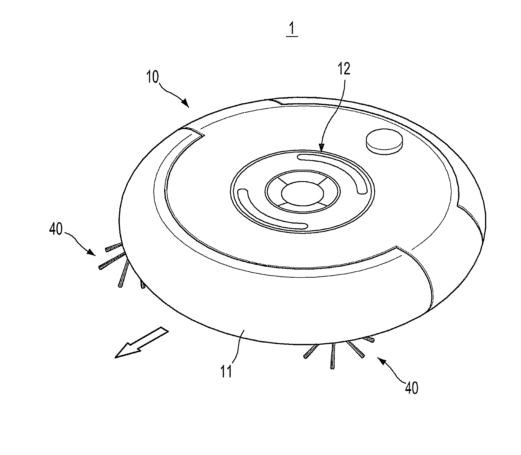
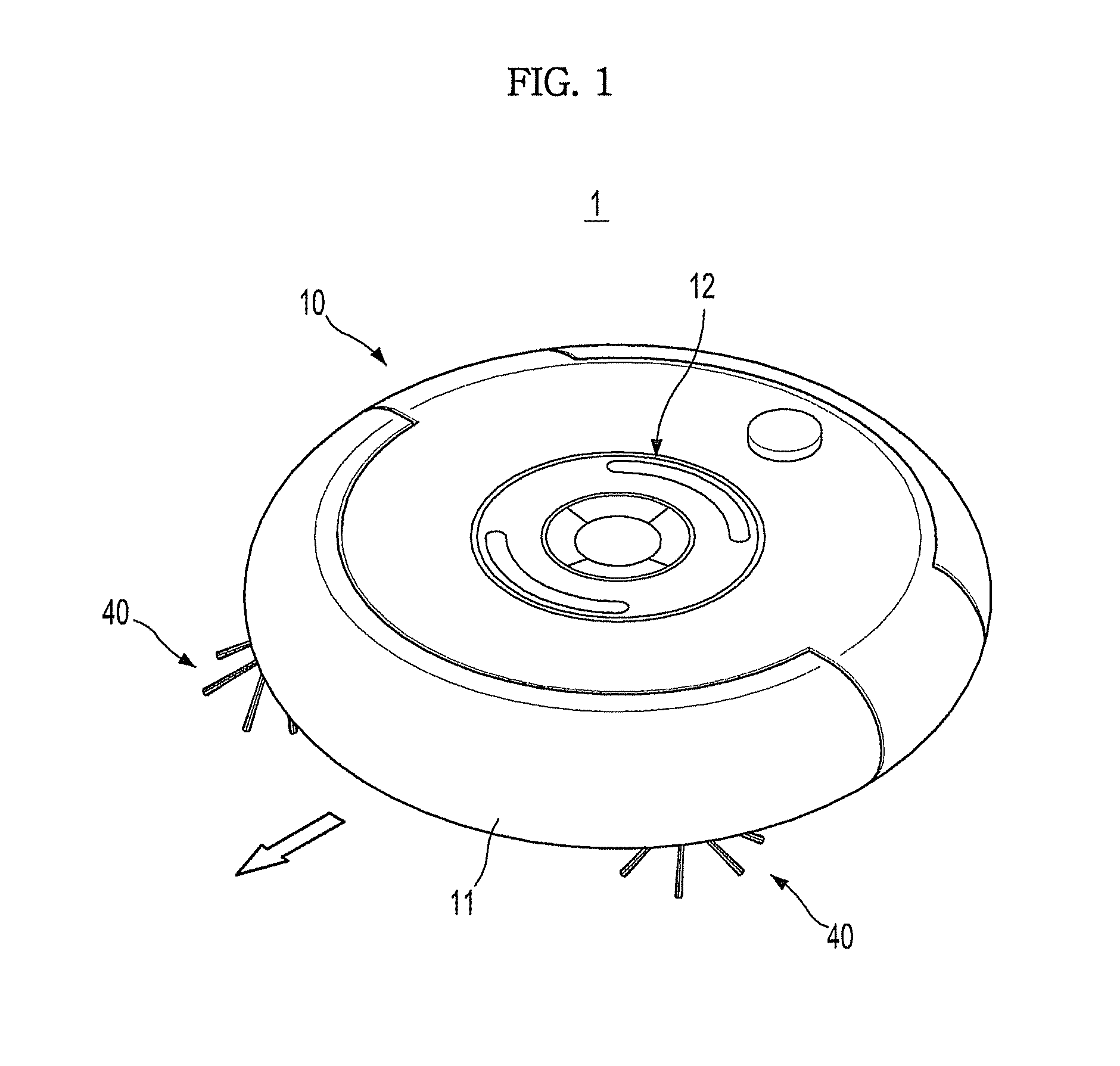
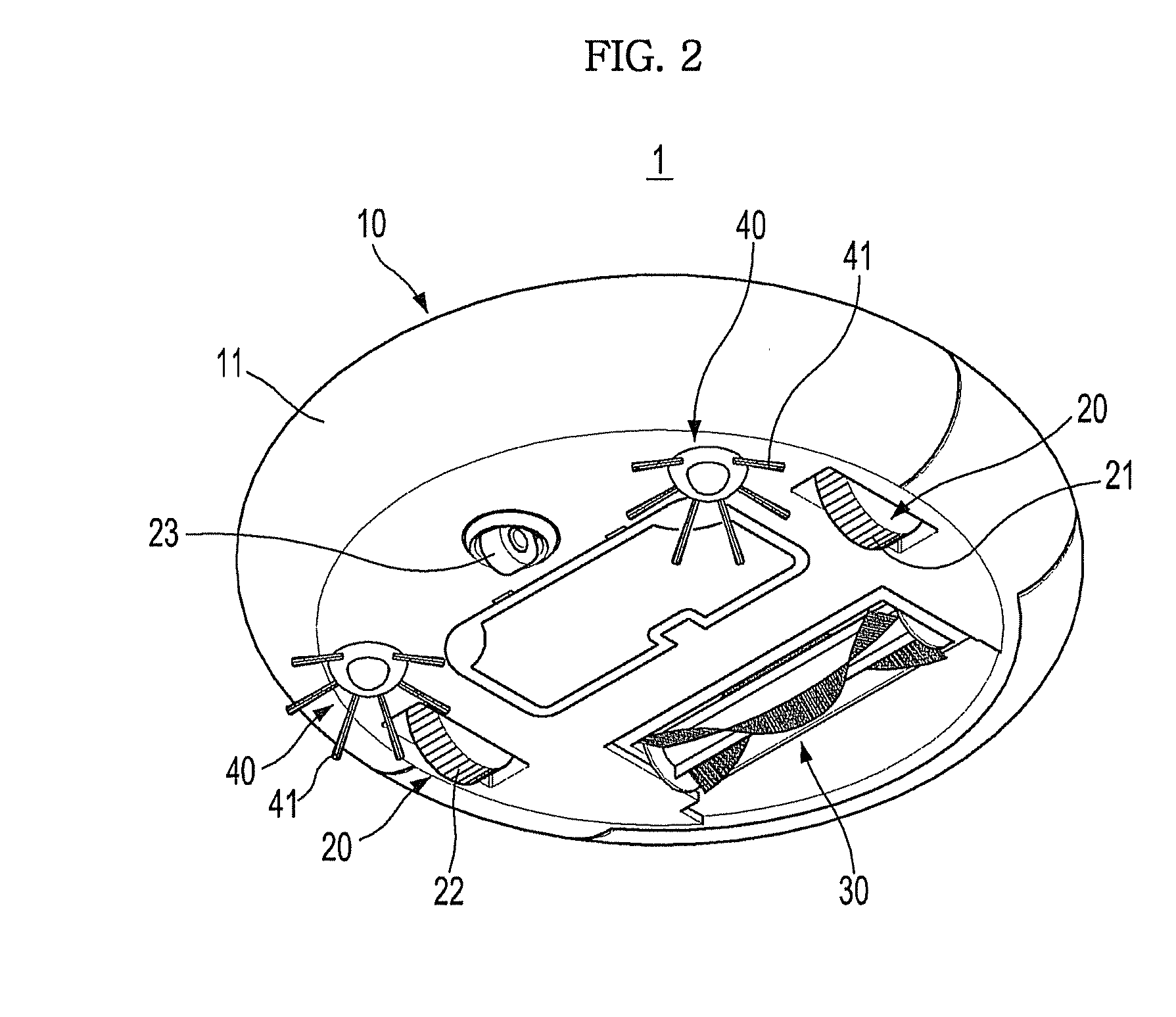
[0034]FIG. 1 is a top perspective view of a robot cleaner in accordance with one embodiment, FIG. 2 is a bottom perspective view of the robot cleaner in accordance with the embodiment, FIG. 3 is a bottom view of the robot cleaner in accordance with the embodiment, and FIG. 4 is a perspective view of a brush unit in accordance with the embodiment.

[0035]As shown in FIGS. 1 to 4, a robot cleaner 1 in accordance with this embodiment includes a main body 10 forming the external appearance of the robot cleaner 1, a driving device 20 installed at the lower portion of the main body 10 to move the robot cleaner 1, and brush devices 30 and 40 to sweep or disperse dust on a floor, on which the robot cleaner 1 travels, to clean the floor.

[0036]Further, a contact sensor and a proximity sensor together with...


PUM


Abstract

Disclosed herein are a robot cleaner that has an improved traveling performance, and a method of controlling traveling thereof. The robot cleaner allows driving wheels, which move the robot cleaner, and a brush unit, which sweeps dust on a floor, to be rotated in the same direction.

Description

CROSS-REFERENCE TO RELATED APPLICATIONS[0001]This application claims the benefit of U.S. Patent Ser. No. 61 / 186,529, filed on Jun. 12, 2009 in the USPTO and Korean Patent Application No. 2009-0079131, filed on Aug. 26, 2009 in the Korean Intellectual Property Office, the disclosures of which are incorporated herein by reference.BACKGROUND[0002]1. Field[0003]Embodiments relate to a robot cleaner that has an improved traveling performance, and a method of controlling traveling thereof.[0004]2. Description of the Related Art[0005]In general, a robot cleaner is an apparatus that sucks foreign substances, such as dust, from a floor while traveling on its own in a region to be cleaned without user manipulation, and thus performs a cleaning operation.[0006]In such a robot cleaner, a pair of driving wheels is installed at both sides of the lower portion of a main body, and causes the main body to move forward or backward or to be rotated. The robot cleaner easily moves forward or backward o...

Claims


Application Information

Patent Timeline
IPC IPC(8): B08B7/00
CPCA47L7/02A47L9/0411A47L2201/00A47L2201/04A47L2201/06
Inventor LEE, JUN HWAJOO, JAE MANJEUNG, SAM JONGSONG, JEONG GONKIM, DONG WONHONG, JUN PYOKO, JANG YOUNCHUNG, WOO RAMYOO, KYUNG HWAN
Owner SAMSUNG ELECTRONICS CO LTD
Why Eureka
Try Eureka