Activation apparatus, method, and computer program for brainwave interface system

Active Publication Date: 2010-12-16
PANASONIC CORP
View PDF3 Cites 73 Cited by
  • Summary
  • Abstract
  • Description
  • Claims
  • Application Information

AI Technical Summary

Benefits of technology

[0020]With an electroencephalogram interface system according to the present invention, a visual stimulation for activation of an electroencephalogram interface (an icon on a screen, an LED, etc.) is flickered, and it is first determined whether a user is paying attention to the visual stimulation, based on an N100 component of an event-related potential since the timing of presenting the visual stimulation as a starting point. Then, based on the determination result (specifically, when it is determined that the user is paying attention to the visual stimulation), the user's will of activation is determined based on whether a P200 componen

Problems solved by technology

However, it has been difficult to execute a manipulation when both hands are unavailable, due to tasks

Method used


Image

  • Activation apparatus, method, and computer program for brainwave interface system
  • Activation apparatus, method, and computer program for brainwave interface system
  • Activation apparatus, method, and computer program for brainwave interface system

Examples


embodiment 1

[0083]Hereinafter, the construction and operation of an activation apparatus for activating an electroencephalogram interface will be described.

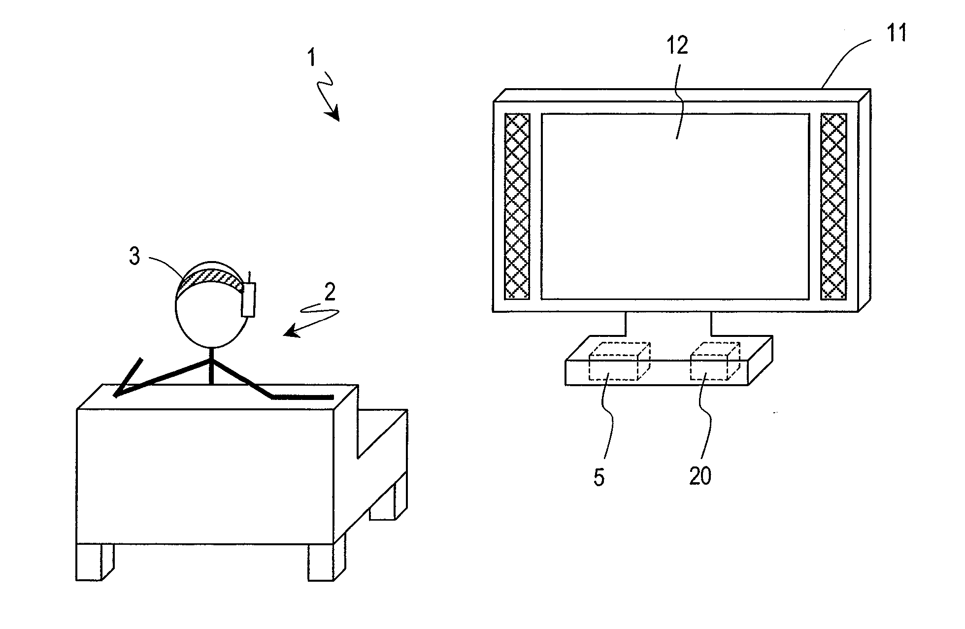
[0084]FIG. 4 shows a construction and an environment of use for an electroencephalogram interface system 1 according to the present embodiment. In the present embodiment, the electroencephalogram interface system 1 includes an electroencephalogram measurement section 3 and a function control section 5.

[0085]The functions of the electroencephalogram interface system 1 will be generally described. First, an output section 6 causes a menu selection screen to be displayed on a TV screen 12, and the electroencephalogram measurement section 3 measures an electroencephalogram signal from a user 2. The function control section 5 analyzes an event-related potential contained in the measured electroencephalogram signal, and outputs to the output section 6 a function control signal for controlling a function of a device (TV set 11). As a result of this...

embodiment 2

[0140]In Embodiment 1, every time an icon flickers, the P200 component of the event-related potential is extracted and a determination as to whether there is a will of activation is made. In the present embodiment, in order to further improve the accuracy of the determination of activation, a step of determining whether flickering of the icon is being watched or not on the basis of the event-related potential is provided before operation of the activation determination section 4, and when flickering of an icon is not being looked at, it is excluded from the target of identification for the determination of activation, thus realizing a reduction in device operations that are unintended by the user.

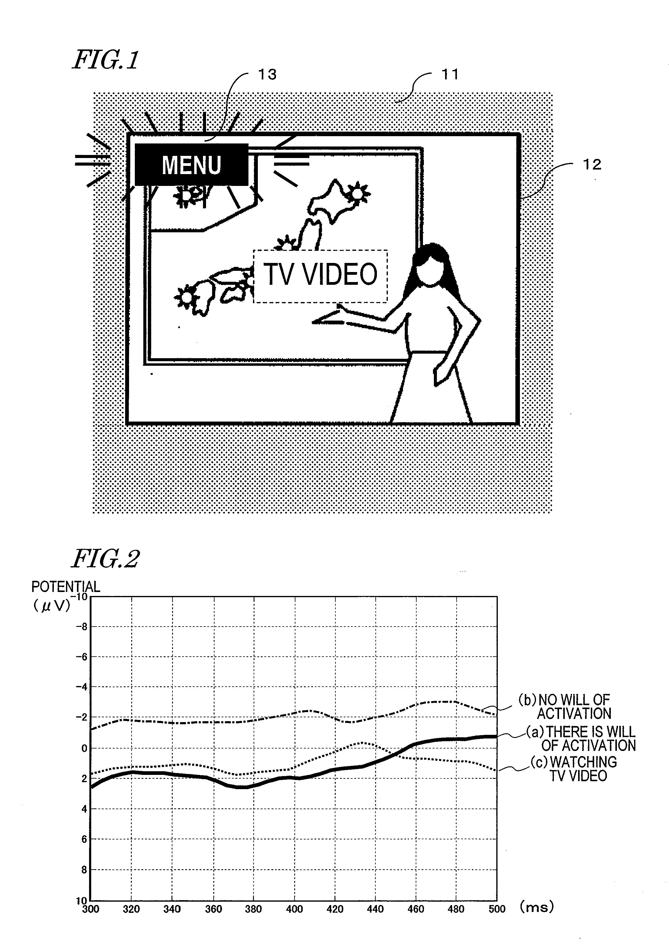
[0141]For example, as shown in FIG. 15(a), when it is determined that the user 2 is not watching the icon 13, the icon 13 is undergoing relatively small flickers in an upper left portion of the TV screen 12 of the TV set 11. On the other hand, as shown in FIG. 15(b), when it is determined t...

embodiment 3

[0162]Embodiments 1 and 2 illustrate examples where the flickering of an icon which serves as a stimulation is controlled by the electroencephalogram interface system, and the device to be manipulated is presenting the stimulation via an output section. However, there is a large number of devices to be utilized in our lives, and it would be very difficult to control the flickering of all such devices.

[0163]Therefore, in the present embodiment, an activation interface will be described which is applicable even in the case where each device performs flickering with its own timing, rather than the flicker timing being collectively controlled by the electroencephalogram interface system.

[0164]In our lives, we encounter various flickering devices, e.g., signboards, neon advertisements, and electronic bulletin board systems. These are flickering with the purpose of catching the eyes of customers, and the final purpose of an advertiser who has installed a signboard or an advertisement is t...


PUM


Abstract

A brain wave interface (IF) is started up using user's brain wave signals. A brain wave IF system comprises a brain wave measuring portion for measuring brain wave signals, a function controlling portion which analyzes an event-related potential contained in brain signals and outputs a function control signal for controlling the function of the apparatus based on the analysis results, and an output portion for outputting the function control signal. A start-up device comprises a start-up judging portion and a stimulus-attention judging portion. The start-up judging portion transmits, to the output portion, a stimulus control signal for controlling presentation/extinction of a visual stimulus which is a single item in the output portion when the brain wave IF system is not working, and compares a value of a P200 component of the event-related potential starting on a presentation timing of a visual stimulus out of the brain wave signals acquired from the brain wave measuring portion with a predetermined threshold value to determine whether or not to output a start-up trigger to the function controlling portion based on the comparison results. The stimulus-attention judging portion judges whether the user is paying attention to the visual stimulus based on an N100 component of the event-related potential starting on the presentation timing of the visual stimulus and makes the start-up judging portion start processing according to the judgment results. The brain wave IF system is started by the start-up judging portion outputting the start-up trigger.

Description

TECHNICAL FIELD[0001]The present invention relates to an interface with which devices are manipulated by utilizing an electroencephalogram (electroencephalogram interface system). More specifically, the present invention relates to an activation apparatus which is incorporated in an electroencephalogram interface system for selecting and activating a desired function by utilizing the electroencephalogram of a user, an activation method, and a computer program which is executed on such an activation apparatus.BACKGROUND ART[0002]Various devices have been proposed in our lives. While living among such devices, users enjoy desired information or services by manipulating the devices. Because of an increase in the number of devices themselves, an increase in the information that cannot be obtained without using devices, and so on, the importance of improving the manipulability of such interfaces is increasing year after year. In information devices (television sets, mobile phones, PDAs, ...

Claims


Application Information

Patent Timeline
IPC IPC(8): A61B5/0476
CPCG06F3/015A61B5/04842A61B5/378
Inventor TERADA, YOSHIHISAADACHI, SHINOBUMORIKAWA, KOJI
Owner PANASONIC CORP
Why Eureka
Try Eureka