

Implanted nerve electrical stimulation control method, device and system
A technology of a control device and a control method, which is applied in artificial respiration, physical therapy, etc., can solve problems such as the inability to program an implanted nerve electrical pulse generator in real time, and achieve the effect of high safety and simple operation
- Summary
- Abstract
- Description
- Claims
- Application Information
AI Technical Summary
Problems solved by technology
Method used
Image

Examples
no. 1 example
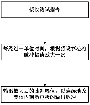
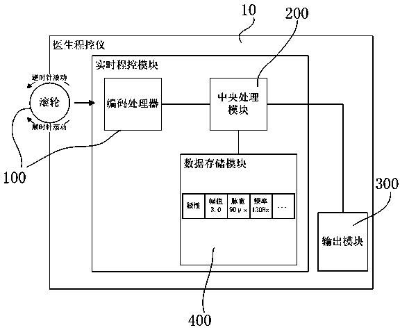
[0080] Amplitude variables are preset in the doctor programmer 10 or the pulse generator 20 . After the doctor programmer 10 or the pulse generator 20 receives the test instruction through the input module provided thereon, every time a unit time passes, the pulse amplitude in the last unit time is added to the pulse amplitude variable, as the output pulse amplitude. For example, the initial pulse amplitude is 0V, the preset unit time is 1 second, and the preset amplitude variable is 0.1V, then after receiving the test command, change the pulse amplitude to 0V+0.1 after 1 second V=0.1V; after 1 second, the system will automatically add an amplitude variable of 0.1V on the basis of 0.1V, and the pulse amplitude at this time is 0.1V+0.1V=0.2V..., and so on. Of course, it is also possible to change the pulse amplitude to 0.1V immediately after receiving the test command, and after 1 second, add an amplitude variable of 0.1V on the basis of 0.1V, and the pulse amplitude at this t...
no. 2 example
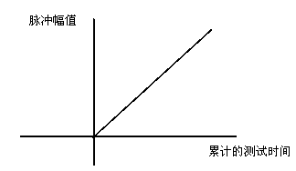
[0082] Amplitude variables within the physician programmer 10 or the pulse generator 20 . Different from Embodiment 1, in this embodiment, if Figure 4 As shown, there is a linear relationship between the pulse amplitude (V) and the accumulated test time (S). The relationship can be expressed through the function algorithm: pulse amplitude (V) = initial pulse amplitude (V) + accumulated test time (S) * amplitude variable (V), generally, in the initial state, the initial If the pulse amplitude is 0, the function algorithm can be expressed as: pulse amplitude (V) = accumulated test time (S) * amplitude variable (V). For example, if the initial pulse amplitude is 0, the accumulated test time is 0.1S, and the amplitude variable is 1V, then the output pulse amplitude is 0.1V; continue testing, when the accumulated test time is 0.2S, the output pulse The amplitude is 0.2V..., and so on. Wherein, the accumulated test time (S)=unit time (S)×n, where n is a positive integer.
no. 3 example
[0084] The difference from Example 1 is that, if Figure 5 As shown, there is a nonlinear relationship between the pulse amplitude and the number of times per unit time in this embodiment. As the number of elapsed unit time increases, its amplitude variable will gradually decrease. For example, after the unit time passes for the first time, the amplitude variable added is 4V, after the unit time passes for the second time, the amplitude variable added is 3V, and after the unit time passes for the third time, the amplitude variable added is It is 2.5V..., and so on.
[0085] Generally, the stimulation pulse for the patient to produce side effects on the stimulating electrode is about 6~8V, so, according to the technical solution of this embodiment, when the pulse amplitude is small, a rapid test can be performed by increasing the pulse amplitude. , and when the pulse amplitude is large, a more accurate test is performed by increasing the pulse amplitude smaller.
PUM
 Abstract
Description
Claims
Application Information