
Screw-in ground anchor

a screw-in, ground anchor technology, applied in the direction of heat collector mounting/support, bulkhead/pile, structural elements, etc., can solve the problems of limited protection against loosening and unscrewing, and achieve the effect of good protection against loosening

Inactive Publication Date: 2010-12-23
KELLNER PETER
View PDF14 Cites 26 Cited by
  • Summary
  • Abstract
  • Description
  • Claims
  • Application Information

AI Technical Summary

Benefits of technology

[0007]It is therefore an object of the invention to provide a screw-in ground anchor with which it is possible to achieve good protection against loosening and unscrewing.
[0008]The invention can be used to anchor a variety of structural elements in the soil. Examples of such structural elements are traffic signs, advertising panels, solar arrays, conservatories, transmission towers, and a multitude of other structural elements. The invention makes it possible to secure an anchoring device in the soil in a flexible way and without great technical effort.

Problems solved by technology

These are beset by the disadvantage that this design loosens the ground when being screwed into it, so that there is only limited protection against loosening and unscrewing.

Method used


Image

  • Screw-in ground anchor
  • Screw-in ground anchor
  • Screw-in ground anchor

Examples


Embodiment Construction

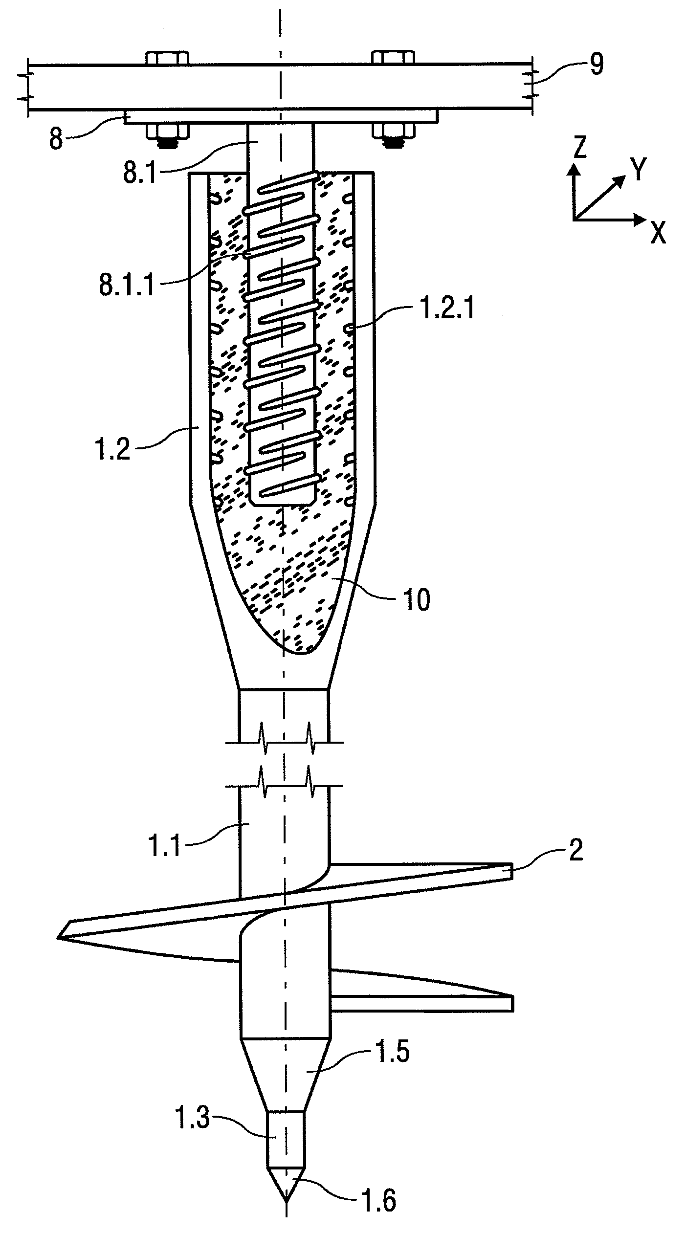
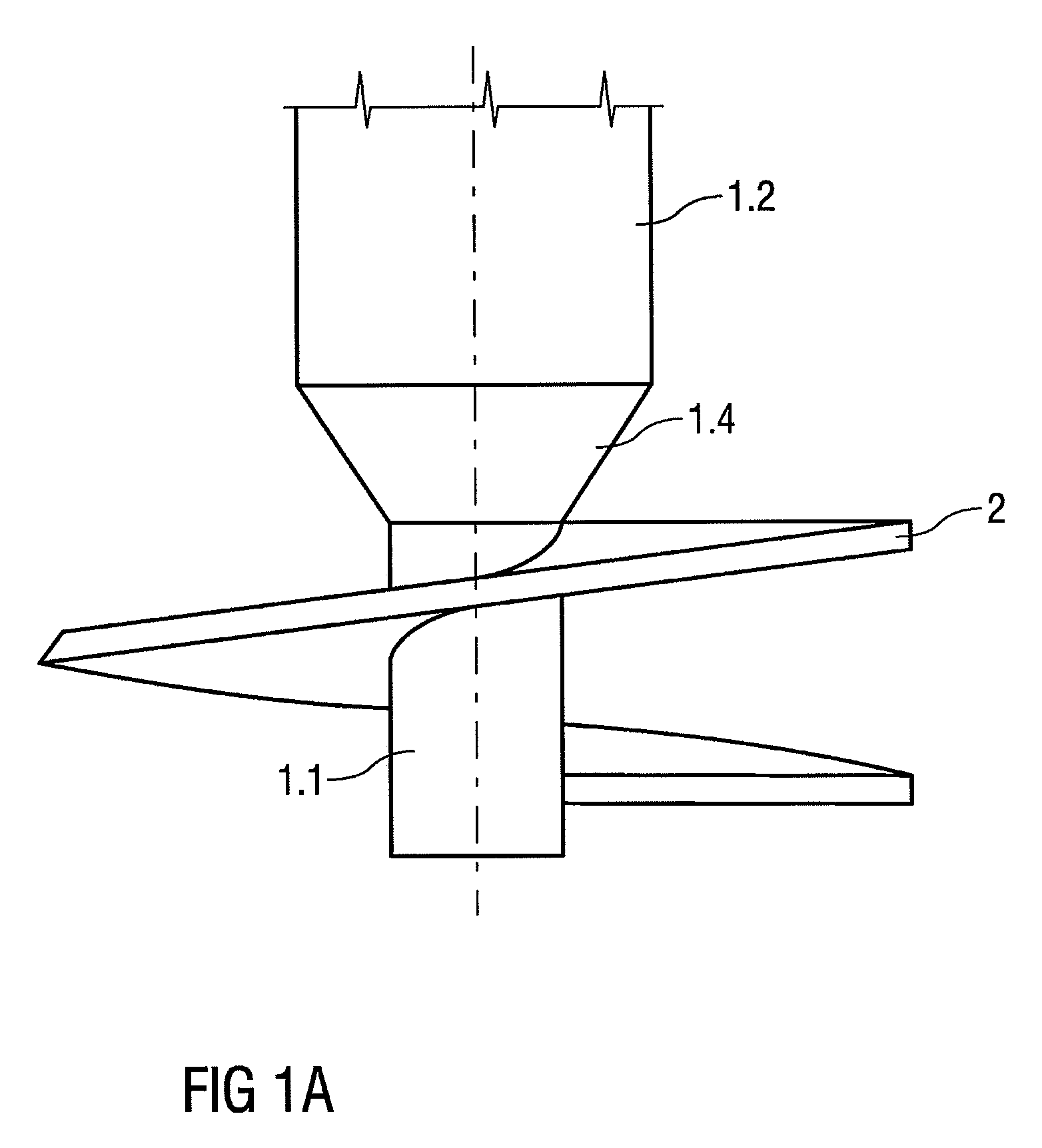
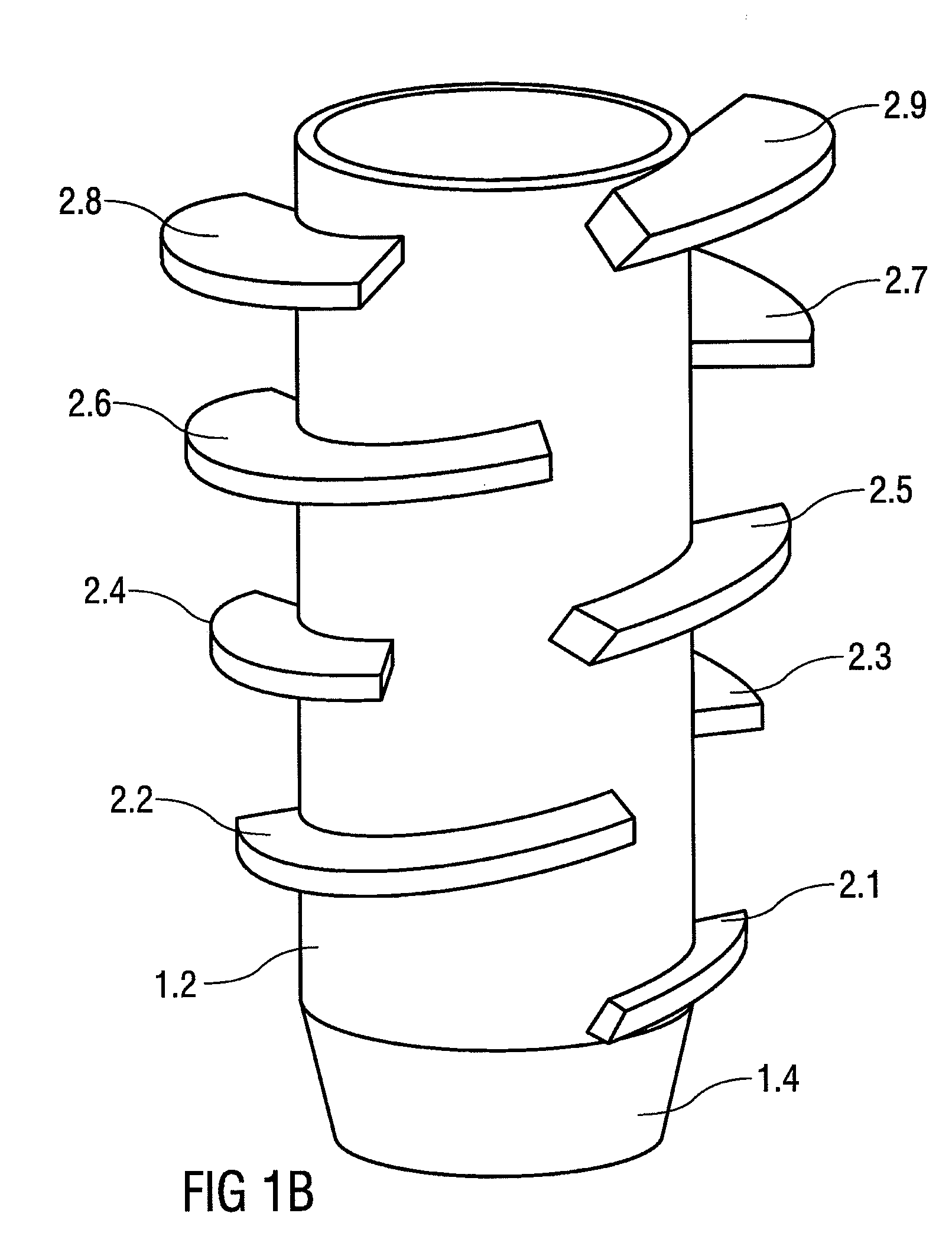
[0036]In the embodiment shown in FIG. 1A, the cutting blade 2 is welded to the lower cylindrical region 1.1 of the base member 1. In the case shown, the cutting blade 2 is designed in the form of a one-piece helix. However, it is also possible to attach the cutting blades as blade segments. The cutting blade 2 is manufactured as a forged or cast component, and is subsequently welded to the base member 1. It is ensured by this means that the pitch of the cutting blade 2 has a uniformly constant value, so that the ground is not loosened when the screw-in ground anchor is screwed in. The screwing-in process is facilitated by the different diameters of the cylindrical regions 1.1 and 1.2, while firm pressure of the upper region 1.2 against the soil is nevertheless ensured, since the soil is compressed with the aid of the conical section 1.4 located between the lower region 1.1 and the upper region 1.2. The base member 1 is designed in the form of a tube, and is open at the bottom end. F...


PUM


Abstract

A foundation driller for anchoring of components in soil is provided that includes an apparatus in which the foundation driller comprises a base body with at least one cylindrical area and at least one cutting blade that provides forward advancement, in which the base body comprises at least two cylindrical areas with different diameters, wherein the area nearer to the soil has a smaller diameter and the at least one cutting blade providing forward advancement is attached at the area nearer to the soil and has an even incline.

Description

[0001]This nonprovisional application is a continuation of International Application No. PCT / EP2009 / 052091, which was filed on Feb. 20, 2009, and which claims priority to: German Patent Application Nos. DE 10 2008 011 869.9, which was filed in Germany on Feb. 29, 2008; to DE 10 2008 022 458.8 which was filed in Germany on May 8, 2008; and to DE 10 2008 026 215.3 which was filed in Germany on May 30, 2008; and which are all herein incorporated by reference.BACKGROUND OF THE INVENTION[0002]1. Field of the Invention[0003]The invention relates to a screw-in ground anchor for anchoring structural elements in the soil, having a base member with at least one cylindrical region and having at least one cutting blade that produces forward motion.[0004]2. Description of the Background Art[0005]Numerous embodiments of such screw-in ground anchors are known. A screw-in ground anchor described in DE 198 36 370 C2, which corresponds to U.S. Pat. No. 7,007,910, has, on its end facing the earth, a c...

Claims


Application Information

Patent Timeline
Patent Type & Authority Applications(United States)
IPC IPC(8): E02D5/74
CPCE02D5/801E04H12/2223Y02E10/47F24J2/525E04H12/2269F24S25/617
Inventor KELLNER, PETER
Owner KELLNER PETER
Learn More