Hydraulic system with improved pulsation damping

a pulsation damping and hydraulic system technology, applied in hydraulic systems, rotary clutches, braking systems, etc., can solve problems such as pulsation damping measures which are known in principle suffer from disadvantages, haptic feedback, pedal vibration, etc., to improve pulsation reduction, reduce pulsation effect, and reduce pulsation effect.

Active Publication Date: 2010-12-23
CONTINENTAL TEVES AG & CO OHG
View PDF4 Cites 21 Cited by
  • Summary
  • Abstract
  • Description
  • Claims
  • Application Information

AI Technical Summary

Benefits of technology

[0009]It is an object of the present invention to develop generic hydraulic systems in such a manner that a unified and cost-effective solution is provided to the problems which arise at very different locations, and that a decrease in comfort as a result of the pulsation effect is prevented.
[0010]The present invention has an advantage that a situation-adjusted, automatic adaptation of the physical characteristics and effects of the damping unit to the prevailing pulsation characteristic is made possible. Because an automatic adaptation of the damper unit to an imposed pulsation characteristic takes place, therefore, no fixed working point of the damping unit is defined. As a result, pulsation reduction is improved, because the effect of the damping measure is extended over a widened operating range. This makes possible an extended range of action, which covers both high pressure applications with small delivery volumes and high delivery volumes with low pressure.

Problems solved by technology

For example, the noise insulation in the interior of modern motor vehicles is optimized to such an extent that, for example, haptic feedback—such as, in particular, brake pedal vibration—intrudes especially negatively and is found objectionable.
Pulsation damping measures which are known in principle suffer from the disadvantage that they operate satisfactorily only at certain points.
This dimensioning has a negative effect in a pulsation evaluation and on noise behavior, especially when comparatively small delivery volumes are called for.
The negative pressure can liberate separated gas portions, leading to undesired compressibilities in the brake system.

Method used


Image

  • Hydraulic system with improved pulsation damping
  • Hydraulic system with improved pulsation damping
  • Hydraulic system with improved pulsation damping

Examples


Embodiment Construction

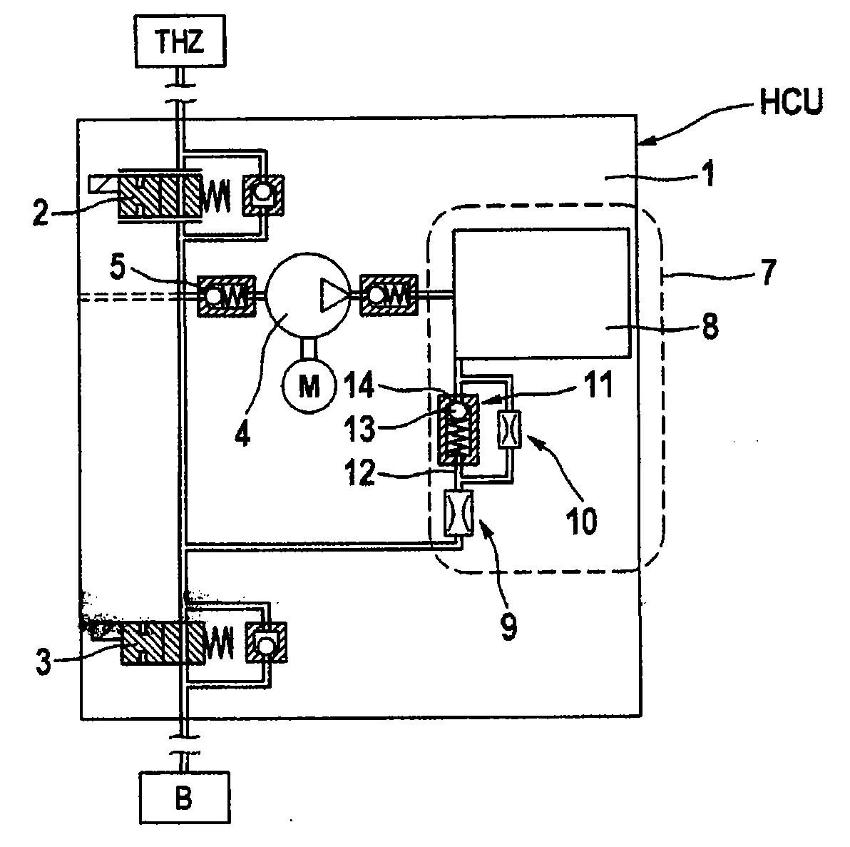
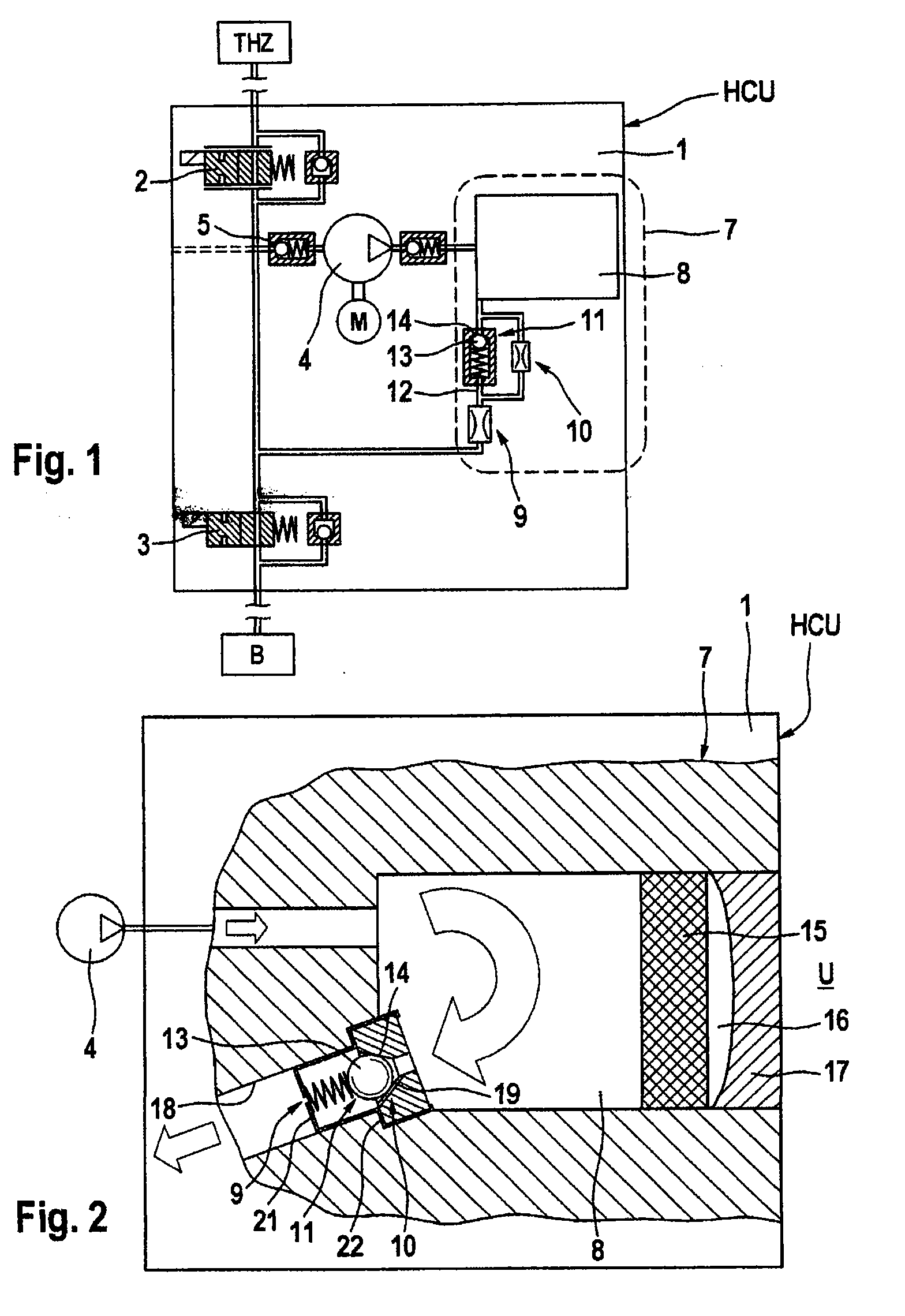
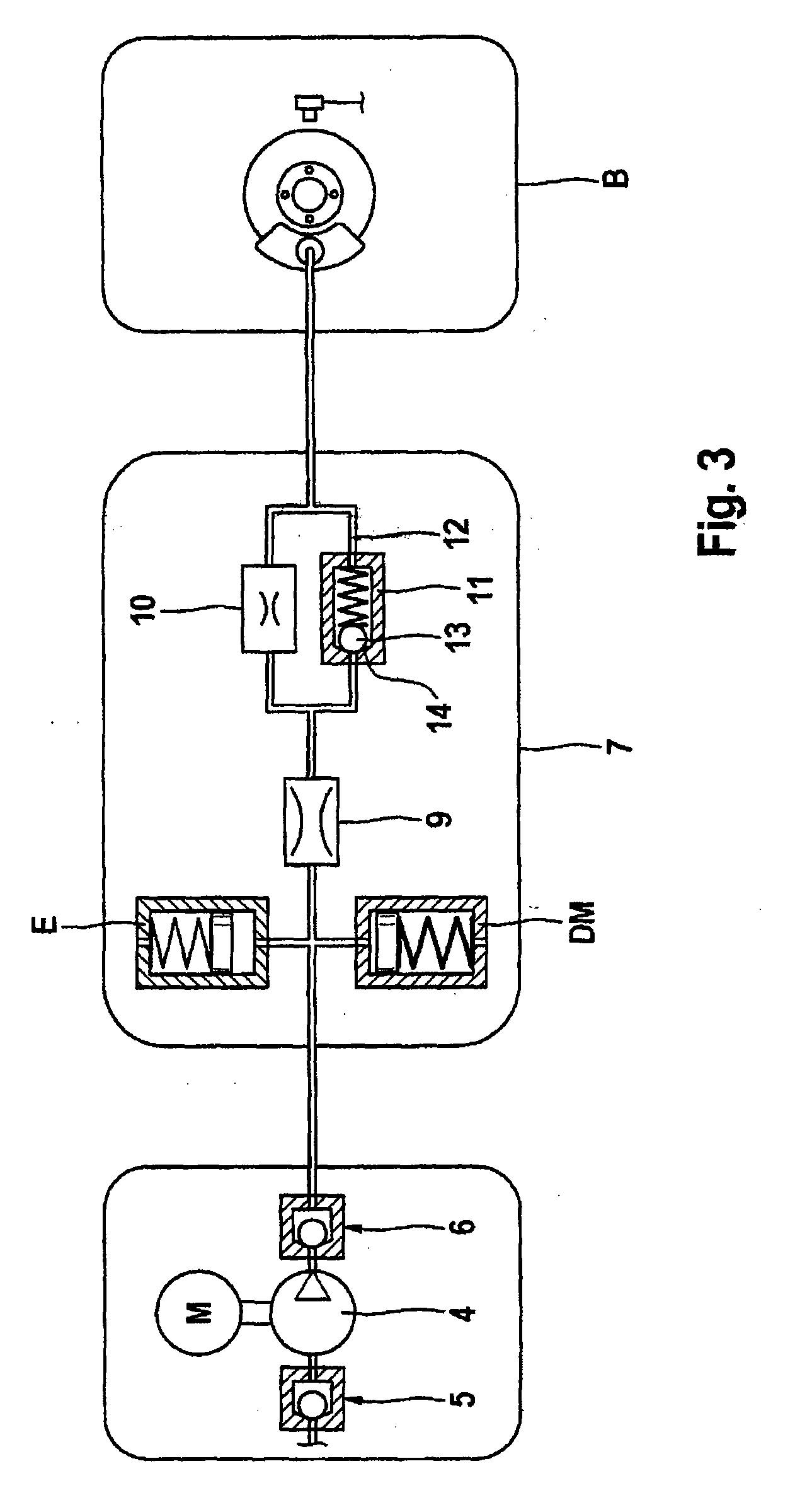
[0019]FIG. 1 will be discussed in detail below. This figure shows schematically and partially a hydraulic system HCU with a receiving body 1 for electrohydraulic valves 2, 3 and a pump 4, which may be a reciprocating piston pump, which is arranged between an actuation unit THZ (master cylinder with reservoir) and wheel brakes B (load). The hydraulic system HCU makes possible a pressure modulation. The pump 4 is electric-motor driven. A speed variable motor M may be used, so that the delivery rate can be regulated. A suction path of the pump 4 includes an intake valve 5 which is controlled either by pressure differential or electromagnetically. In addition, the suction path is configured to be switchable by means of a currentlessly closed reversing valve (not shown) in such a manner that pressure medium can be drawn either from the actuation unit THZ or from a low-pressure accumulator (not shown), which in principle is connected to an outlet of a wheel brake B. Furthermore, the elect...


PUM


Abstract

A hydraulic system comprising a receiving body with electrohydraulic valve, with at least one hydraulic pump, and with channels for connecting the pump to at least one hydraulic load. A pulsation situation arises as a result of the delivery of a pressure medium by the pump and / or as a result of pressure medium being withdrawn by the load. At least one damping unit is provided, having a plurality of pulsation damping means such as, in particular, a damping chamber, and orifice. The hydraulic system provides a uniform and cost-effective solution for different operating situations and prevents a decrease in comfort. The damping unit has at least one switching means for adjusting the action of said damping unit to a varied pulsation situation by connecting or disconnecting one or more damping means.

Description

CROSS REFERENCE TO RELATED APPLICATIONS[0001]This application is the U.S. national phase application of PCT International Application No. PCT / EP2009 / 051277, filed Feb. 4, 2009, which claims priority to German Patent Application No. DE 10 2008 008 271.6, filed Feb. 8, 2008, and German Patent Application No. 10 2009 006 980.1, filed Jan. 30, 2009, the contents of such applications being incorporated herein by reference.FIELD OF THE INVENTION[0002]The invention relates to a hydraulic system with improved pulsation damping, comprising a receiving body with electrohydraulic valves, with at least one hydraulic pump, and with channels for connecting the pump to at least one hydraulic load, a pulsation situation arising as a result of delivery of pressure medium by the pump and / or as a result of withdrawal of pressure medium by the load, and there being provided at least one damping unit which comprises a plurality of pulsation damping means such as a damping chamber, elastic body and orifi...

Claims


Application Information

Patent Timeline
Patent Type & Authority Applications(United States)
IPC IPC(8): F15B13/00
CPCB60T8/4068B60T8/40B60T8/42
Inventor KLEY, RONALDSCHMITT, STEFAN
Owner CONTINENTAL TEVES AG & CO OHG
Why Eureka
Try Eureka