Hoop lock

a technology of hoop lock and lock body, which is applied in the field of hoop lock, can solve the problems of undesirably large lock body width, undesirably complex design, and high manufacturing cost, and achieve the effect of simplifying the handling of locks, increasing the access to locking mechanisms, and facilitating the use of locking mechanisms

Active Publication Date: 2010-12-23
ABUS AUGUST BREMICKER SOEHNE AG
View PDF16 Cites 1 Cited by
  • Summary
  • Abstract
  • Description
  • Claims
  • Application Information

AI Technical Summary

Benefits of technology

[0026]To be able to fix the lock particularly simply to the object to be secured in the case of the explained L-shaped design of the hoop, it is further preferred if the named reception gap extends parallel to the direction of movement of the hoop or at an acute angle thereto, i.e. at an angle <45°. A specific oblique position is particularly advantageous in the case of an embodiment of the hoop lock as a brake disk lock since the handling is hereby simplified, in particular the actuation of the locking mechanism, when the lock is fixed to a brake disk of a vehicle wheel.
[0027]When a k

Problems solved by technology

The lock housing hereby, however, has an undesirably complex design and is accordingly expensive in manufacture.
In addition, the lock body has a width which is undesirably

Method used


Image

  • Hoop lock
  • Hoop lock
  • Hoop lock

Examples


Embodiment Construction

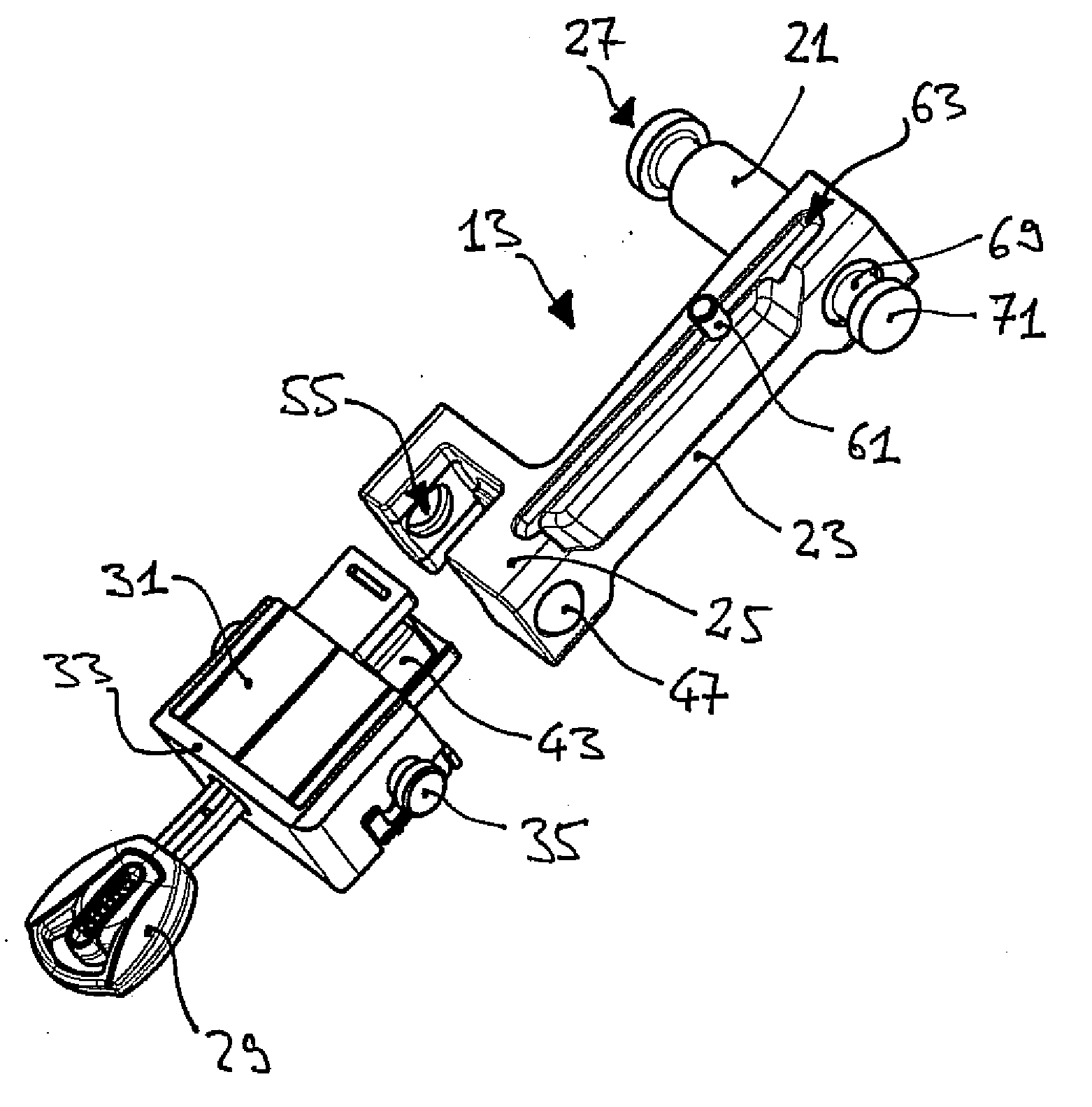
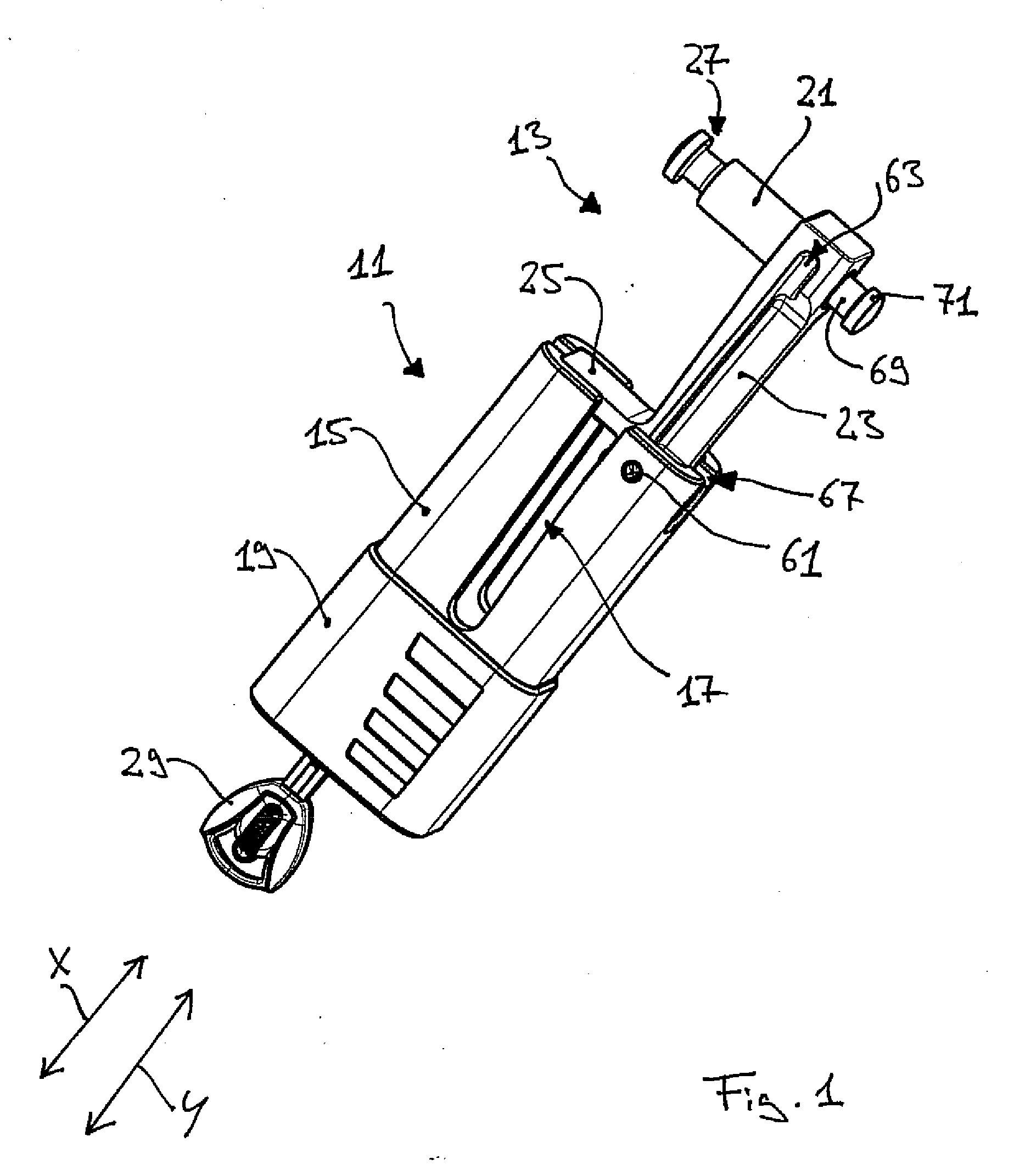
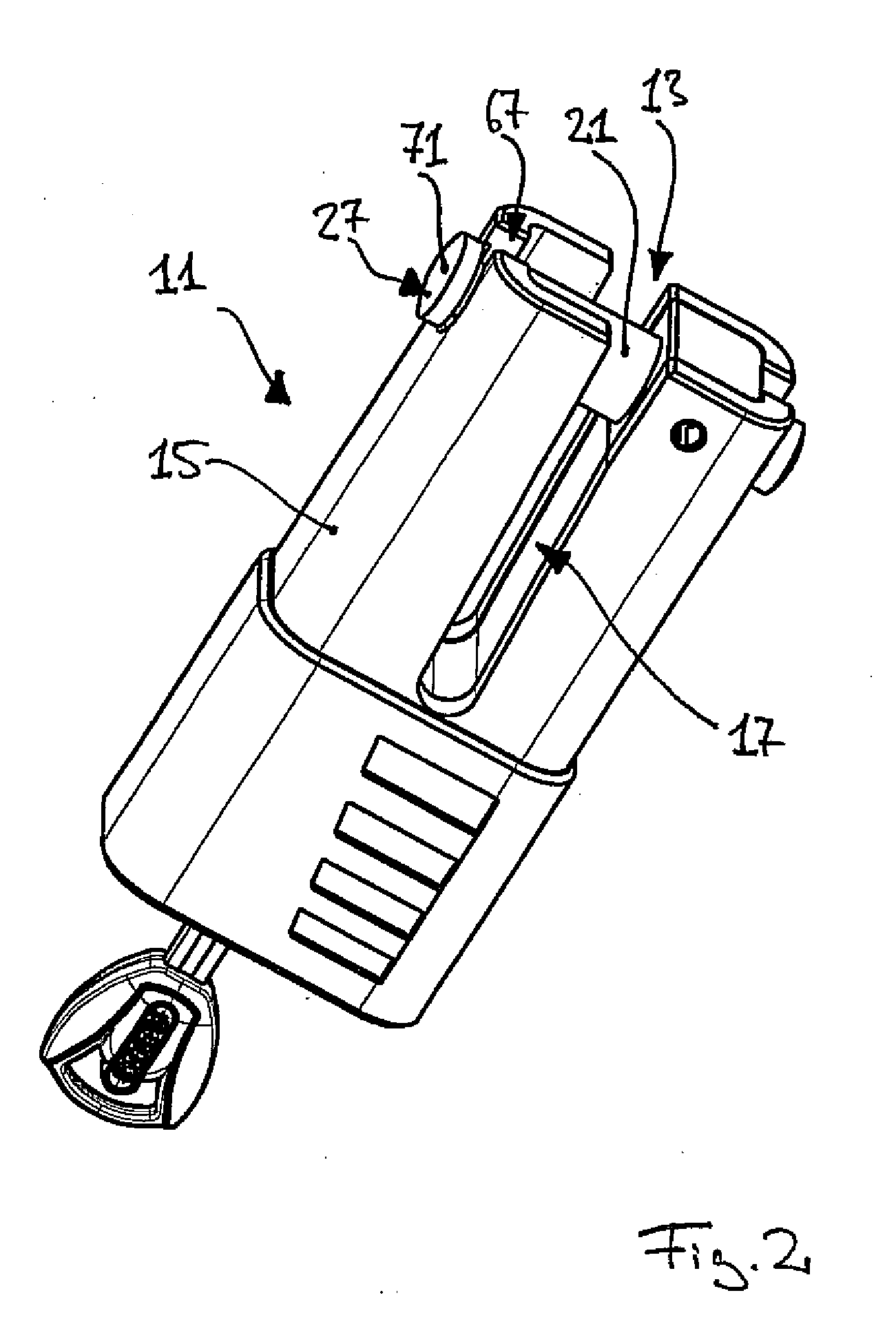
[0037]FIGS. 1 and 2 show a hoop lock which is made as a brake disk lock and has a lock body 11 and a hoop 13. The hoop 13 is supported movable in translation at the lock body 11. FIG. 1 shows the hoop 13 in an open position, whereas FIG. 2 shows the hoop 13 in an closed position.

[0038]The lock body 11 has an outer housing 15 which is formed by a tubular section having a substantially rectangular cross-section and rounded edges. The longitudinal axis of the outer housing 15 corresponds to the direction of movement X of the hoop 13. The outer housing 15 has a reception gap 17 at the end provided for the moving out of the hoop 13.

[0039]The outer housing 15 is provided with a cover 19 of plastic at the other end. With respect to the open position in accordance with FIG. 1, that is when the hoop 13 is moved out of the lock body 11, the hoop 13 substantially has an L-shape outside the lock body 11. The one limb of this L-shape is formed by an elongate securing section 21 in the form of a ...


PUM


Abstract

The invention relates to a hoop lock having a lock body and a hoop which is movable relative to the lock body between an open position and a closed position. The lock body has a lock housing and a closing mechanism which is fastened in the lock housing and has a driver. The driver is selectively movable into an unlatched position or into a latched position. A latching device is furthermore provided in the lock body and acts between the driver of the locking mechanism, the hoop and the lock housing. The latching device latches the hoop to the lock housing when the hoop is in the closed position and the driver of the locking mechanism is in the latched position. At least a part of the latching device is movable together with the hoop between the open position and the closed position of the hoop.

Description

CROSS-REFERENCE TO RELATED APPLICATIONS[0001]This application claims priority of German patent application 10 2009 030 031.7 filed Jun. 23, 2009.FIELD OF THE INVENTION[0002]The invention relates to a hoop lock having a lock body and a hoop which is movable relative to the lock body between an open position and a closed position. The lock body has a lock housing and a closing mechanism which is fastened in the lock housing and has a driver. The driver is selectively movable into an unlatched position or into a latched position. A latching device is furthermore provided in the lock body and acts between the driver of the locking mechanism, the hoop and the lock housing. The latching device latches the hoop to the lock housing when the hoop is in the closed position and the driver of the locking mechanism is in the latched position.BACKGROUND OF THE INVENTION[0003]Such a hoop lock is known, for example, as a padlock which has an essentially U-shaped hoop. The hoop can be guided through...

Claims


Application Information

Patent Timeline
IPC IPC(8): E05B67/28E05B67/02E05B67/30
CPCB62H5/18E05B67/02E05B67/36E05B67/24E05B67/06Y10T70/446Y10T70/489Y10T70/5872Y10T70/413Y10T70/452
Inventor SCHAEFER, HANS-THEO
Owner ABUS AUGUST BREMICKER SOEHNE AG
Why Eureka
Try Eureka