Laser measuring device for narrow slit detection and positioning and measuring method thereof

A technology of laser measurement and laser triangulation, applied in the field of laser vision system, can solve the problems of difficult to accurately locate spatial position, difficult to detect, difficult to achieve, and achieve the effect of improving recognition ability, improving structure and function, and improving contrast.

Pending Publication Date: 2020-03-17
成都绝影智能科技有限公司
View PDF6 Cites 2 Cited by
  • Summary
  • Abstract
  • Description
  • Claims
  • Application Information

AI Technical Summary

Problems solved by technology

Conventional laser seam tracking sensors or laser seam tracking sensors can be used to detect and locate wide conventional seams, but for narrow seams with a seam width less than 0.1mm, it is difficult for conventional laser seam contouring instruments or laser seam tracking sensors to detect; The reason is that the detection laser of the laser profiler or laser seam tracking sensor intersects with the narrow seam during measurement. Since the width of the narrow seam or crack is too narrow, the laser light strip pattern appears as a continuous light strip, which cannot leave a clear gap on the light strip pattern. Intermittent pattern of light bars, making it difficult or even impossible to identify the narrow slits
If a machine vision system is used, although narrow cracks or cracks with a width of less than 0.1 mm can be identified by lighting and other means, this vision system mainly reflects its recognition function, but it is difficult to accurately track and locate narrow cracks or cracks in three-dimensional space
If ultrasonic detection is used, its spatial resolution is not enough, and it is still difficult to precisely locate the spatial position of the narrow slit

Method used


Image

  • Laser measuring device for narrow slit detection and positioning and measuring method thereof
  • Laser measuring device for narrow slit detection and positioning and measuring method thereof
  • Laser measuring device for narrow slit detection and positioning and measuring method thereof

Examples


Embodiment

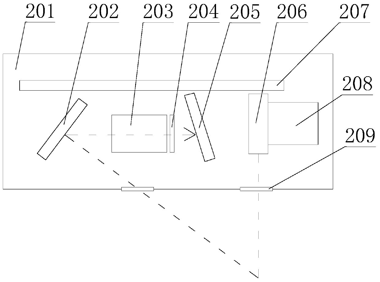
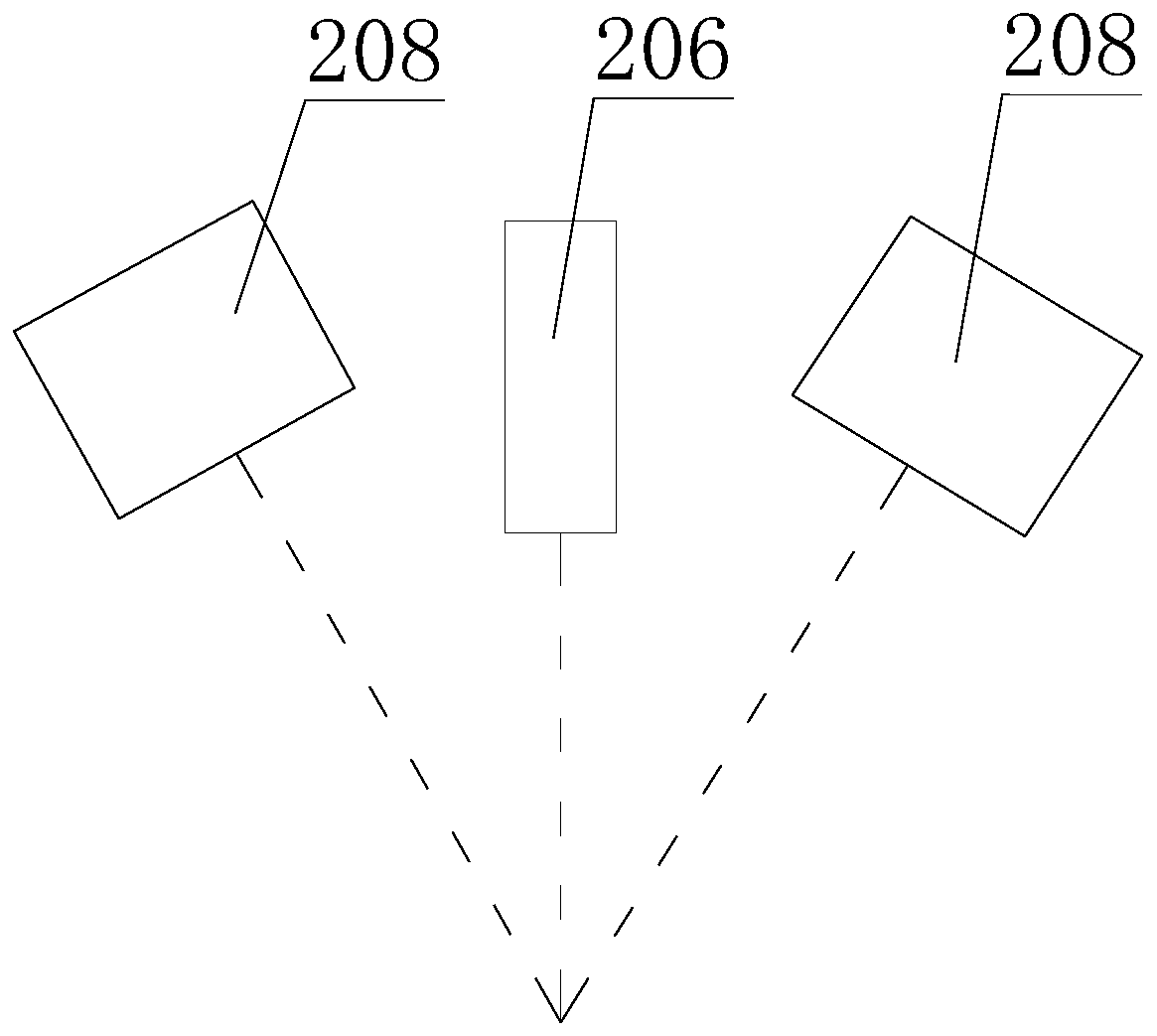
[0030] like figure 1 As shown, this embodiment provides a laser measurement device for slit detection and positioning, including a mechanical housing 201, a laser triangulation optical path disposed inside the mechanical housing 201, a circuit processing unit 207, an auxiliary illumination light source 208, and two windows glass 209;

[0031] The laser triangulation optical path, the circuit processing unit 207 and the auxiliary illumination light source 208 are all arranged inside the mechanical housing 201. In other embodiments, the auxiliary illumination light source can also be arranged outside the mechanical housing. In this embodiment, two pieces of window glass 209 Set at the bottom of the mechanical housing 201 , two pieces of window glass 209 are respectively located at the laser exit and incident positions of the mechanical housing 201 , and the circuit processing unit 207 is connected to the laser triangulation circuit and the auxiliary illumination light source 208...


PUM


Abstract

The invention discloses a laser measuring device for narrow slit detection and positioning and a measuring method thereof, which relate to the technical field of laser vision systems. The laser measuring device comprises a mechanical outer shell, a laser triangulation light path arranged in the mechanical outer shell, a circuit processing unit, an auxiliary lighting source and two pieces of windowglass. The measuring method comprises the steps of: acquiring a slit surface image; extracting a central point connecting line of line-shaped structured light strips and a central point connecting line of slit edges; calculating an intersection point of a central position connecting line of the slit and a central point connecting line of line-shaped structured light; and converting data of a central point of the slit into a coordinate position in a three-dimensional physical space according to a laser triangulation principle, and outputting the result. By identifying and positioning the three-dimensional positions of slits or fine cracks, the laser measuring device and the measuring method thereof can be used for guiding the robot to track the slits, such as fine weld joint tracking, crack detection and tracking and gluing gap tracking, and solve the technical problem perplexing the industry.

Description

technical field [0001] The invention relates to the technical field of laser vision systems, in particular to a laser measuring device and a measuring method for detecting and locating a slit. Background technique [0002] In industrial manufacturing, it is often necessary to detect and locate narrow or fine cracks, such as the location of gaps in laser welding, and the tracking of gaps in some electronic products. The width of these narrow slits or tiny cracks is often less than 0.1mm, and some are even of the order of 10um. Conventional laser seam tracking sensors or laser profilers can be used to detect and locate wide conventional gaps, but for narrow gaps with a width of less than 0.1mm, conventional laser profilers or laser seam tracking sensors are difficult to detect; its The reason is that the detection laser of the laser profiler or the laser seam tracking sensor intersects with the slit during measurement. Since the width of the slit or crack is too narrow, the l...

Claims


Application Information

Patent Timeline
Patent Type & Authority Applications(China)
IPC IPC(8): G01N21/01G01N21/95
CPCG01N21/01G01N21/95
Inventor 张明勇
Owner 成都绝影智能科技有限公司
Why Eureka
Try Eureka