Rail vehicle brake slack adjuster

a technology for adjusting brakes and rail vehicles, which is applied in the direction of slack adjusters, railway braking systems, brake elements, etc., can solve the problems of increasing manufacturing difficulties with accompanying greater expenses, causing considerable counter-force at brake application, and unnecessarily large rotating mass, so as to reduce slack, increase slack, and reduce mass

Inactive Publication Date: 2010-12-23
FAIVELEY TRANSPORT NORDIC AB
View PDF9 Cites 13 Cited by
  • Summary
  • Abstract
  • Description
  • Claims
  • Application Information

AI Technical Summary

Benefits of technology

[0011]The thus created slack adjuster is double-acting, i e it has the ability to decrease a slack that has become too large due for example to wear of the brake block in the brake rigging and to increase a slack that has become too small. Besides obviating t

Problems solved by technology

This adjuster, however, has certain drawbacks, of which the most important one is that it contains a powerful spring needed for its adjusting function and creating a considerable counter-force at brake application.
Also, its spindle and nut is combined into one unit creating an unnecessarily great rotating mass.
However, this prior adjuster ha

Method used


Image

  • Rail vehicle brake slack adjuster
  • Rail vehicle brake slack adjuster
  • Rail vehicle brake slack adjuster

Examples


Embodiment Construction

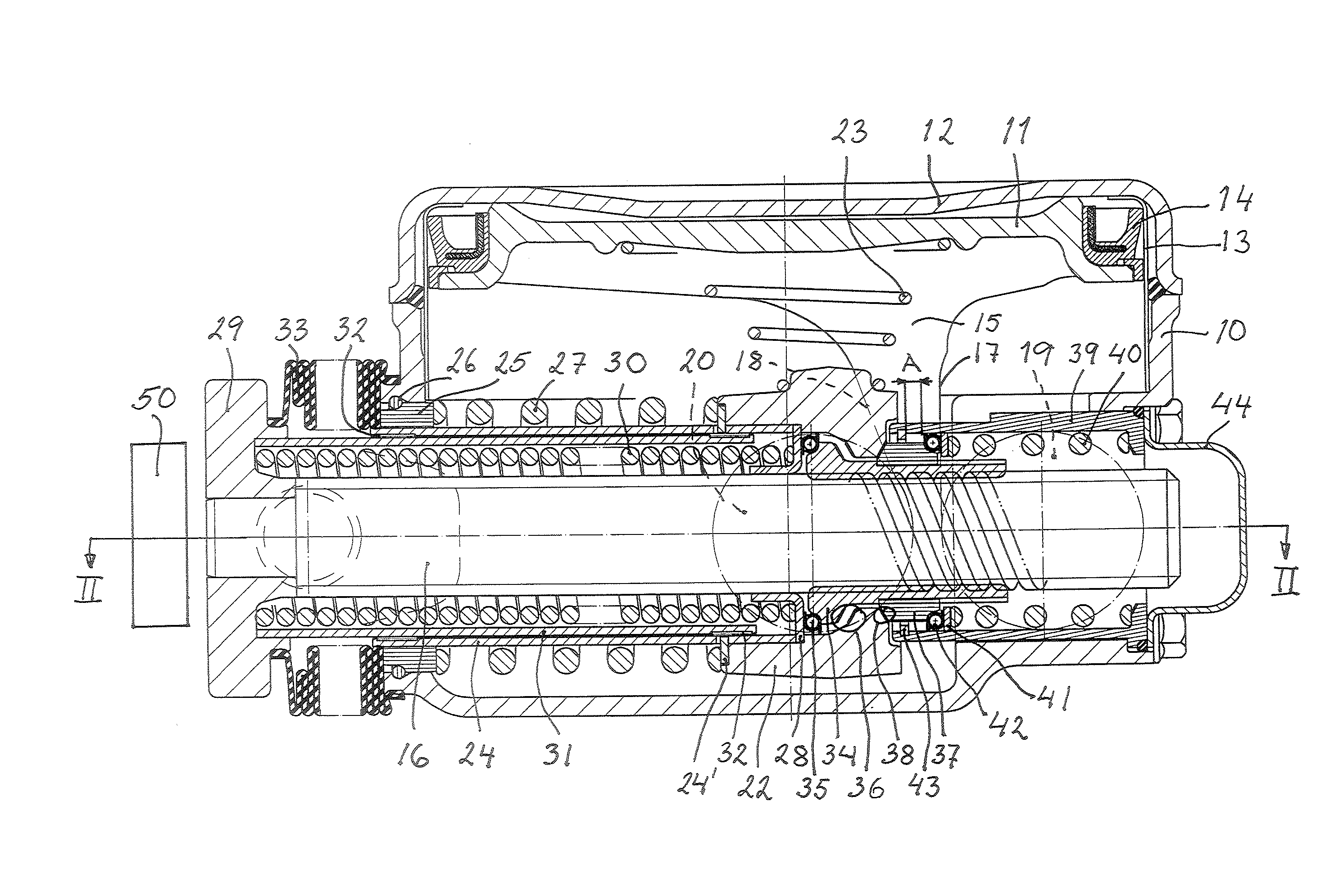
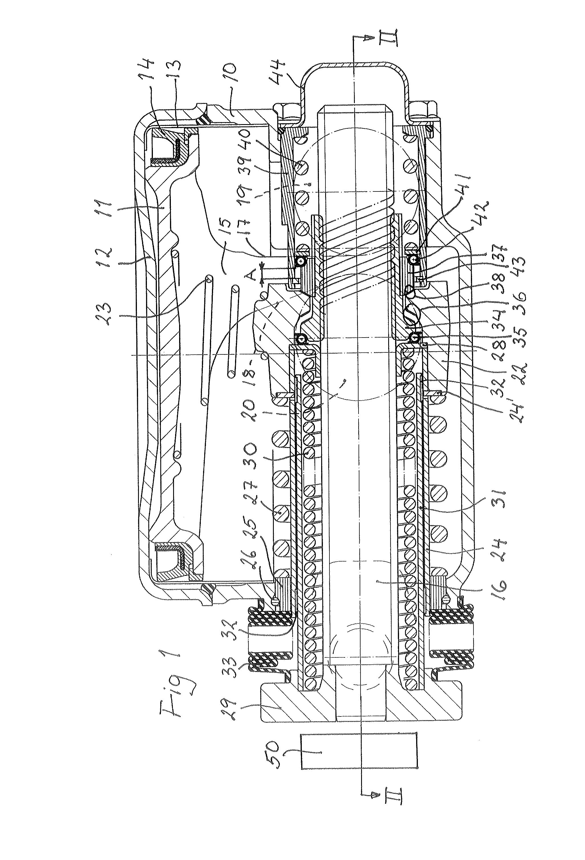
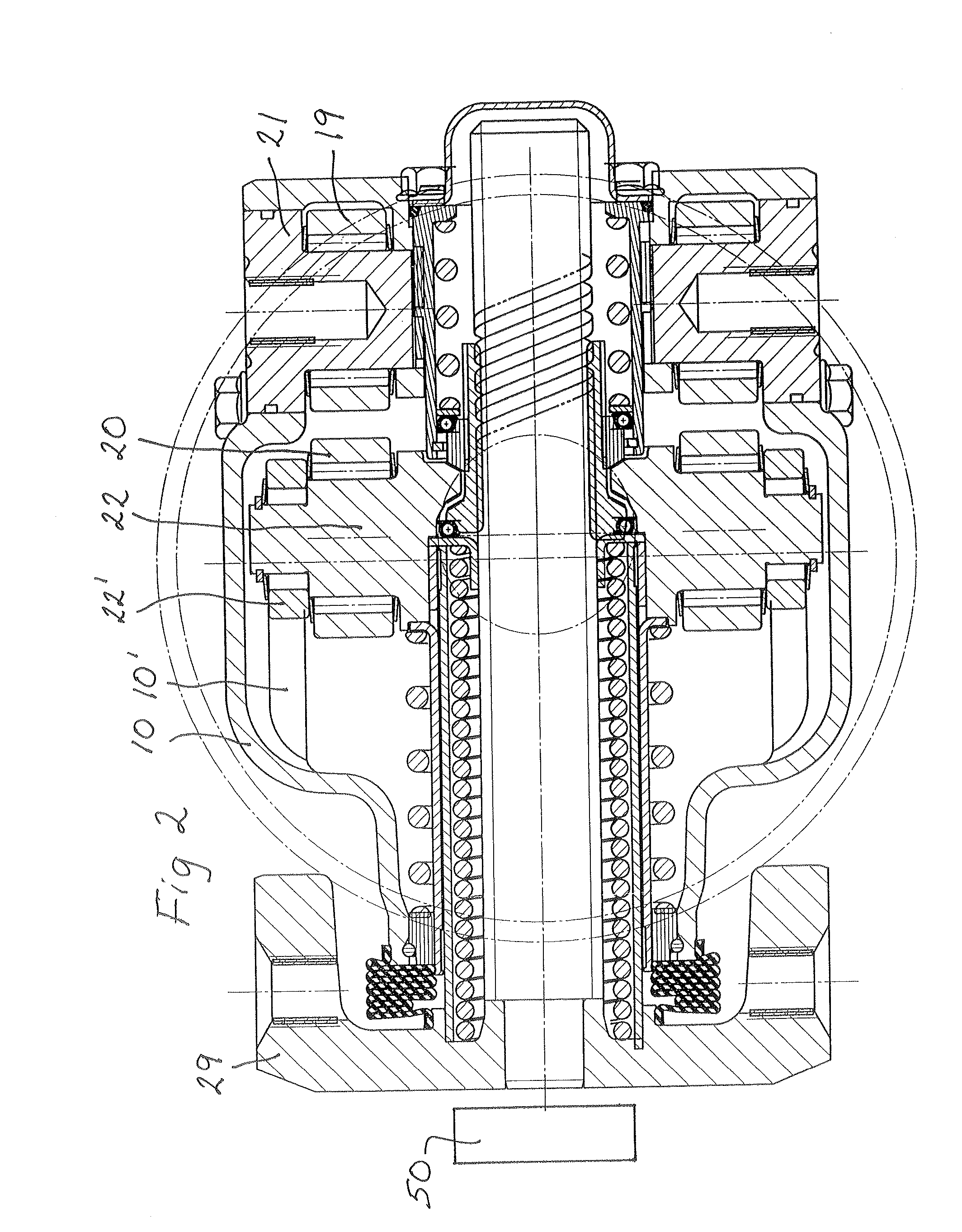
[0022]A brake unit for a rail vehicle is shown in section in FIGS. 1 and 2. A brake unit generally comprises a brake cylinder (or a similar brake actuating means) and a slack adjuster built into a common housing.

[0023]FIG. 1 is provided with all possible reference numerals, whereas such numerals are more sparsely used in FIG. 2 for clarity reasons. When used in this specification, terms like “vertical”, “horizontal”, “below” and “above” are used with reference to the position of the brake unit on the drawings, even if the brake unit when mounted on a rail vehicle may well have other positions.

[0024]The brake unit has a housing 10, which is cylinder-shaped in its upper end. A piston 11 is vertically movably arranged in this cylinder-shaped upper part of the housing 10. A cover 12 above the piston 11 is screwed to the housing 10. A cylinder liner 13 may be arranged, and the piston 11 can be provided with a conventional piston sealing 14.

[0025]At its underside the piston 11 is provided...


PUM


Abstract

A rail vehicle brake slack adjuster comprises an axially movable, sleeve-shaped driver element (22) adapted to receive an axially applied braking force in a brake application direction, a spindle (16) axially movable within the driver element, an adjuster nut (34) in non-self-locking thread engagement with the spindle, clutch means between the driver element and the adjuster nut, and a barrel spring (30) biasing the spindle in the brake application direction. The adjuster has a combination of a first clutch (36) comprising a clutch surface on the driver element (22) directed in the brake application direction and a corresponding clutch surface on the adjuster nut (34) and a second clutch (38) comprising a clutch surface on the driver element (22) directed in the direction opposite to the brake application direction and a corresponding clutch surface on an adjuster nut sleeve (37). The adjuster nut sleeve (37) is axially movable on the adjuster nut (34).

Description

TECHNICAL FIELD[0001]The present invention relates to a rail vehicle brake slack adjuster, comprising an axially movable, sleeve-shaped driver element adapted to receive an axially applied braking force in a brake application direction, a spindle axially movable within the driver element, an adjuster nut in non-self-locking thread engagement with the spindle, clutch means between the driver element and the adjuster nut, and a barrel spring biasing the spindle in the brake application direction.BACKGROUND OF THE INVENTION[0002]Rail vehicle slack adjusters may be divided into two main groups having one or two nuts, respectively, in non-self-locking engagement with the spindle in order to perform the function of adjusting the slack between a brake block or pad and a tread of a wheel or a brake disc to a an intended value.[0003]The present invention relates to an adjuster of the one-nut-type.[0004]There are numerous examples of such adjusters, typical examples being disclosed by EP-A-0 ...

Claims


Application Information

Patent Timeline
IPC IPC(8): B61H15/00F16D65/66
CPCF16D65/56B61H15/0028B61H15/0057F16D65/66
Inventor EMILSSON, FRED
Owner FAIVELEY TRANSPORT NORDIC AB
Why Eureka
Try Eureka