Welding power to auxiliary power conversion system and method

a technology of auxiliary power conversion and welding power, which is applied in the field of welding power sources, can solve the problems of power loss caused by cords and the use of such cables

Active Publication Date: 2010-12-23
ILLINOIS TOOL WORKS INC
View PDF7 Cites 44 Cited by
  • Summary
  • Abstract
  • Description
  • Claims
  • Application Information

AI Technical Summary

Benefits of technology

[0004]The present disclosure is directed to systems and methods relating to an auxiliary power conversion unit for use in a welding system. In some embodiments, the auxiliary power conversion unit is capable of outputting DC as well as AC power and is capable of outputting multiple voltages consistent with the demands of typical auxiliary tools, such as a hand grinder, a light, and so forth. In particular, the present disclosure provides methods and systems for manufacturing and using the auxiliary power conversion unit, which is capable of being remotely located from a welding power supply unit during a welding operation. The power conversion unit is capable of drawing power from an arc potential via an electrode cable and a work cable and is sufficiently portable to facilitate easy replacement or transfer between welding systems. In certain embodiments, the power conversion unit may be a stand-alone system or may be incorporated into a device, such as a wire feeder, which is configured to derive power from the arc potential. In some embodiments, the power conversion unit may include an interface that includes a display panel configured to display operating parameters, such as the level of power output, the mode of operation, and so forth, to the user. The power conversion unit may contain control and processing electronics that may include a controller, a processor, memory, and so forth.

Problems solved by technology

However, the welding power source may be located far from the location of the weld creation.
It is now recognized that this may inconveniently necessitate the use of extension cords that carry the auxiliary power from the welding power source to the location of the weld creation.
It is now recognized that these extension cords contribute to power losses since the power may be transferred long distances.
Further, inefficiencies may result from the use of such cables due to misplacement, borrowing, and theft of the extension cables.

Method used


Image

  • Welding power to auxiliary power conversion system and method
  • Welding power to auxiliary power conversion system and method
  • Welding power to auxiliary power conversion system and method

Examples


Embodiment Construction

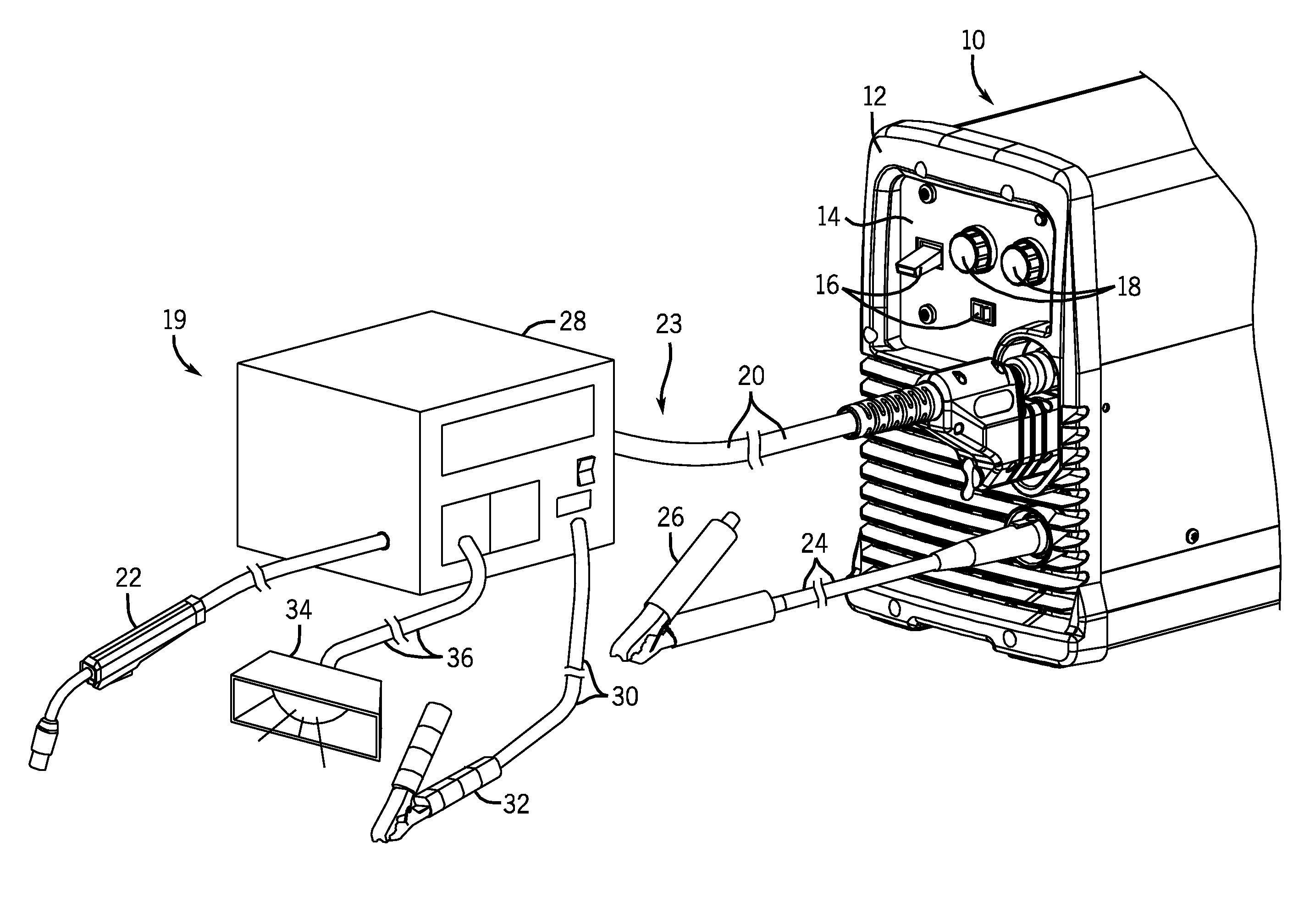
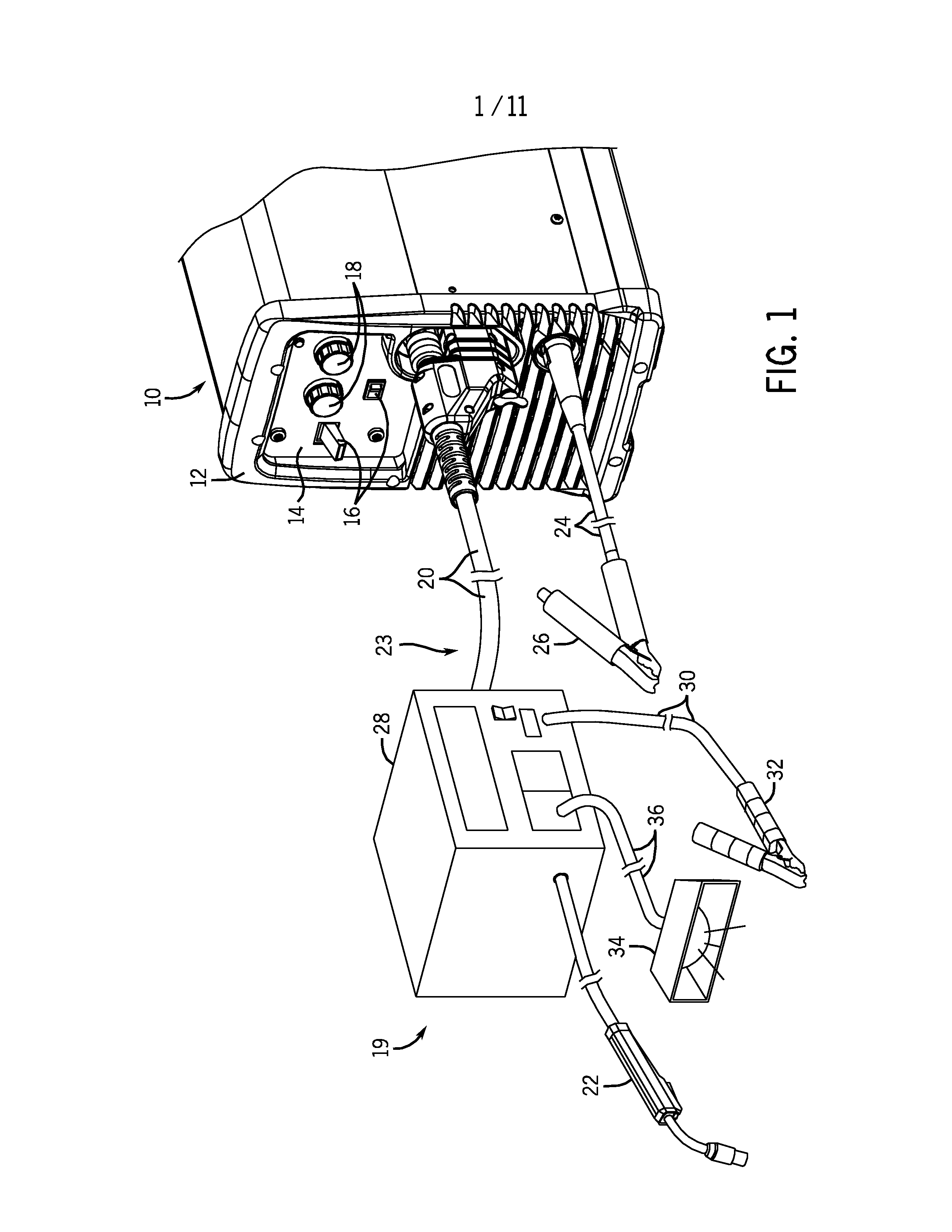
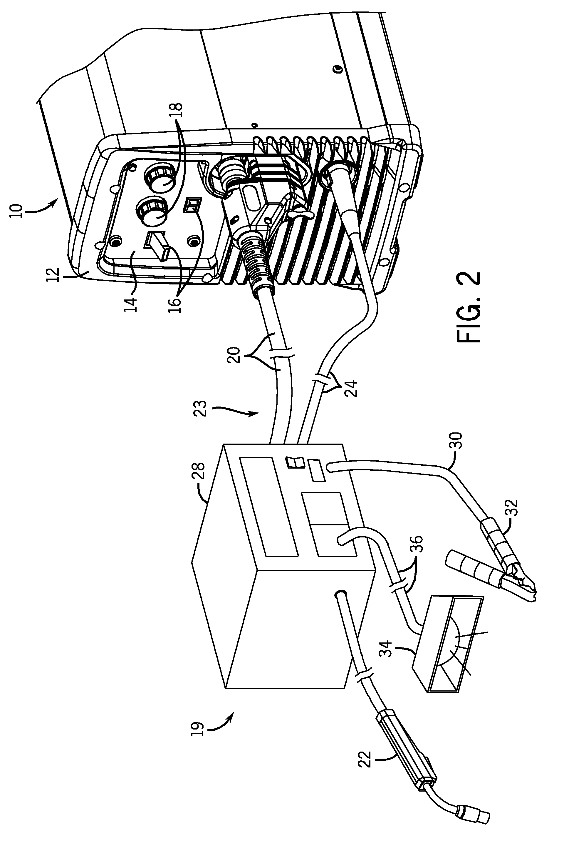
[0017]As discussed in further detail below, various embodiments of an auxiliary power conversion unit for use in a welding system are provided in accordance with present embodiments. The auxiliary power conversion unit is electronic, capable of outputting DC as well as AC power, and capable of outputting multiple voltages (e.g. 115V, 230V, etc.) consistent with the demands of typical auxiliary tools (e.g. hand grinder, light, etc.). The auxiliary power conversion unit is also capable of being remotely located from a welding power supply unit during a welding operation. The power conversion unit is capable of drawing power from an arc potential via an electrode cable and a work cable and is sufficiently portable to facilitate easy replacement or transfer between welding systems. Furthermore, the power conversion unit may be a stand-alone system or may be incorporated into a device, such as a wire feeder, which is configured to derive power from the arc potential.

[0018]The power conve...


PUM

PropertyMeasurementUnit
frequencyaaaaaaaaaa
frequencyaaaaaaaaaa
currentaaaaaaaaaa

Abstract

Methods and systems for manufacturing and using the auxiliary power conversion unit, which is capable of being remotely located from a welding power supply unit during a welding operation, are provided. In some embodiments, the auxiliary power conversion is capable of outputting DC as well as AC power, capable of outputting multiple voltages consistent with the demands of typical auxiliary tools, such as a hand grinder or a light. In certain embodiments, the power conversion unit may be a stand-alone system or may be incorporated into a device, such as a wire feeder, which is configured to derive power from the arc potential. The power conversion unit may contain control and processing electronics that may include a controller, a processor, memory, and so forth.

Description

BACKGROUND[0001]The present disclosure relates generally to welding power sources, and more particularly, to systems and methods for providing auxiliary power at the location of the weld.[0002]Welding is a process that has increasingly become ubiquitous in all industries. While such processes may be automated in certain contexts, a large number of applications continue to exist for manual welding operations. While the power requirements of the weld creation process remain central to a manual welding operation, additional auxiliary power requirements may also be necessary for weld joint preparation and clean up. For instance, lights, hand grinders, torch cooler pumps, and so forth, may require an additional 115V or 230V AC output.[0003]Some welding power sources provide auxiliary AC outlets to meet this demand. However, the welding power source may be located far from the location of the weld creation. It is now recognized that this may inconveniently necessitate the use of extension...

Claims


Application Information

Patent Timeline
Patent Type & Authority Applications(United States)
IPC IPC(8): B23K9/10
CPCB23K9/1006B23K9/12B23K9/1043
Inventor BORCHERT, NEAL MAYNARDBATZLER, TODD GERALD
Owner ILLINOIS TOOL WORKS INC
Why Eureka
Try Eureka