Anode protection system for shutdown of solid oxide fuel cell system

a fuel cell and anode protection technology, applied in the field of solid oxide fuel cell system protection system, can solve the problems of ni re-oxidation, affecting the operation of fuel cells, and volumetric expansion of the anode layer, and achieve the effect of protecting the integrity of the sofc, preventing ni re-oxidation, and being sufficiently portable to be used

Active Publication Date: 2014-12-30
APTIV TECH LTD
View PDF2 Cites 2 Cited by
  • Summary
  • Abstract
  • Description
  • Claims
  • Application Information

AI Technical Summary

Benefits of technology

[0009]An embodiment of the present disclosure is a SOFC Anode Protection Systems (APS) for a SOFC system. The APS protects the integrity of the SOFC during shutdown or standby operation of the SOFC stack by preventing the re-oxidation of the Ni in the anode layer of the SOFC, as well as being sufficiently portable to be used in a mobile vehicle and cost economical to operate. The APS comprises three subsystems that include a Reductant Supply and Safety Subsystem (Subsystem A), a SOFC Anode Protection Subsystem (Subsystem B), and a Post Combustion and Slip Stream Control Subsystem (Subsystem C).

Problems solved by technology

However, if the supply of fuel gas is lost during a controls upset, malfunction, or sudden fuel cut-off, the Ni in the anode of the SOFC may undergo a re-oxidation, where the Ni reacts with the oxygen in the air diffused from the cathode layer or introduced into the anode chamber to form NiO at temperatures above approximately 350° C. The formation of NiO in the microstructure of the anode results in volumetric expansion of the anode layer, which exerts stress on the overall SOFC structure.
Repeated nickel oxidation and reduction may cause delamination or cracking of the electrolyte of the SOFC.
During this time, it will require a large amount of purging gas and frequent bottle changes to meet the reducing gas consumption demand; therefore using compressed reducing gas system on a mobile system, especially onboard a vehicle, is impractical.

Method used


Image

  • Anode protection system for shutdown of solid oxide fuel cell system
  • Anode protection system for shutdown of solid oxide fuel cell system
  • Anode protection system for shutdown of solid oxide fuel cell system

Examples


Embodiment Construction

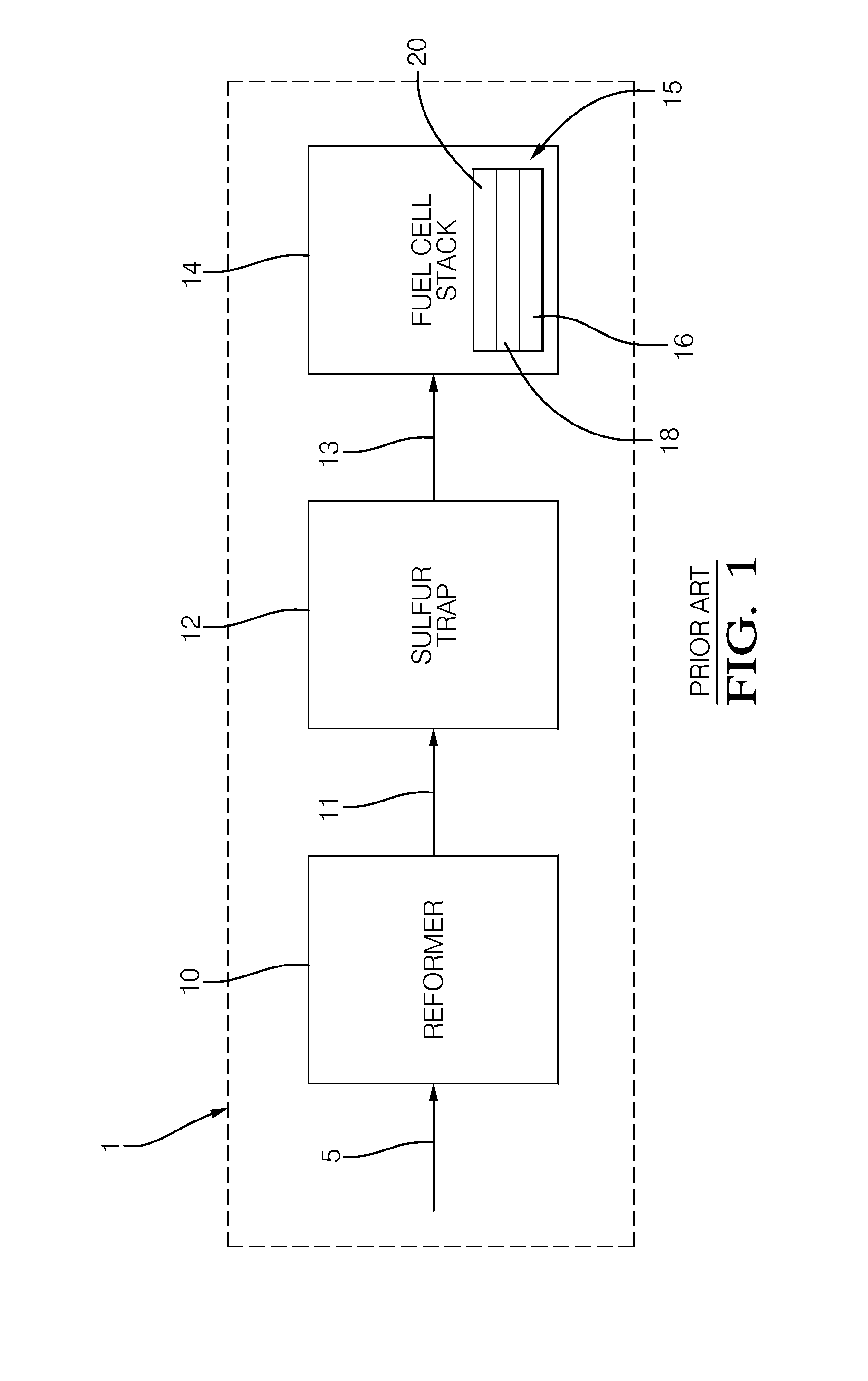
[0022]Shown in FIG. 1 is a typical solid oxide fuel cell (SOFC) system 1 known in the art. The SOFC system 1 includes a reformer 10, an optional desulfurizer 12, and a SOFC stack 14. The SOFC stack 14 includes a plurality of SOFC 15, wherein each SOFC 15 includes an anode layer 16, a cathode layer 20, and an electrolyte layer 18 sandwiched between the anode layer and cathode layer. The reformer 10 is typically of that of a catalytic hydrocarbon reformer that receives a hydrocarbon fuel stream 5 and produces fuel gas that includes hydrogen. The hydrocarbon fuel stream 5 may be that of gasoline, diesel, natural gas, jet fuel, kerosene, alcohol, ether, ammonia, or the likes. The three types of reformer technologies that are typically employed in conjunction with the SOFC system 1 are endothermic reformers using water or high recycle as inputs, autothermal reformers using partial air and partial recycle as inputs, and partial oxidation reformers using air an input. The reformer 10 takes...


PUM

PropertyMeasurementUnit
temperatureaaaaaaaaaa
internal pressureaaaaaaaaaa
electrical potentialaaaaaaaaaa

Abstract

An Anode Protection Systems for a SOFC system, having a Reductant Supply and safety subsystem, a SOFC anode protection subsystem, and a Post Combustion and slip stream control subsystem. The Reductant Supply and safety subsystem includes means for generating a reducing gas or vapor to prevent re-oxidation of the Ni in the anode layer during the course of shut down of the SOFC stack. The underlying ammonia or hydrogen based material used to generate a reducing gas or vapor to prevent the re-oxidation of the Ni can be in either a solid or liquid stored inside a portable container. The SOFC anode protection subsystem provides an internal pressure of 0.2 to 10 kPa to prevent air from entering into the SOFC system. The Post Combustion and slip stream control subsystem provides a catalyst converter configured to treat any residual reducing gas in the slip stream gas exiting from SOFC stack.

Description

GOVERNMENT-SPONSORED STATEMENT[0001]This invention was made with the United States Government support under Contract DE-FC-26-08NT-0003894 awarded by the U.S. Department of Energy. The Government has certain rights in this invention.TECHNICAL FIELD OF INVENTION[0002]The present disclosure is related to a solid oxide fuel cell system; more particularly, a system for the protection of the anode of a solid oxide fuel cell.BACKGROUND OF INVENTION[0003]Fuel cells are used to produce electricity when supplied with fuels containing hydrogen and an oxidant such as air. A typical fuel cell includes an ion conductive electrolyte layer sandwiched between a cathode layer and an anode layer. There are several different types of fuel cells known in the art, one of which is a solid oxide fuel cell (SOFC). SOFCs are regarded as a highly efficient electrical power generator that produces high power density with fuel flexibility and are used in Auxiliary Power Units (APU) to convert hydrocarbon fuels...

Claims


Application Information

Patent Timeline
Patent Type & Authority Patents(United States)
IPC IPC(8): H01M8/04
CPCY02E60/50H01M8/04H01M8/2425H01M8/04223H01M2008/1293H01M8/04231H01M8/04228H01M8/2432
Inventor LI, BOB X.GRIEVES, MALCOLM J.KELLY, SEAN M.
Owner APTIV TECH LTD
Why Eureka
Try Eureka