
Support and holding device for bicycle saddle

a technology for holding devices and bicycle saddles, which is applied in the direction of cycle saddles, cycle frames, cycle equipment, etc., can solve the problems of high weight of these rods, and achieve the effect of high strength, precise and stable locking effect, and easy integration into the shap

Inactive Publication Date: 2010-12-23
SINGENBERGER ROLF +2
View PDF8 Cites 21 Cited by
  • Summary
  • Abstract
  • Description
  • Claims
  • Application Information

AI Technical Summary

Benefits of technology

[0008]The object of the present invention was now to propose a support for bicycle saddles which with the lowest possible weight permits a simple adjustability as well as a reliable attachment of the bicycle saddle.
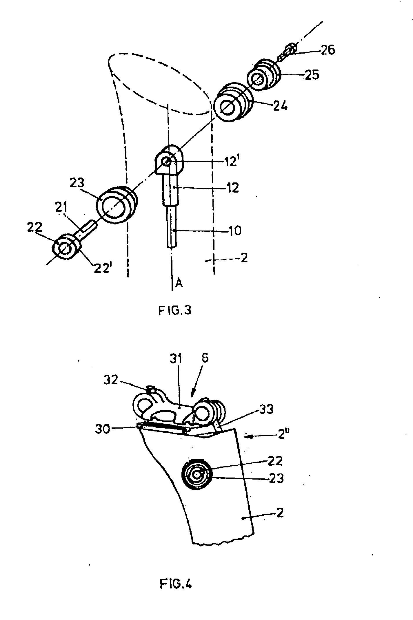
[0024]For example, the saddle carrier is embodied in two parts with a saddle clamp and a hold-down device, wherein the hold-down device is preferably connected to the seat tube by means of two attachment means. Different saddle models can thus be connected universally and easily to the seat tube. If the clamping effect of the saddle carrier is realized via the attachment means, an optimal force transfer into the seat tube can be realized thereby.

Problems solved by technology

These can be met by a corresponding of material selection, which, however, also often results in high weights of these rods.

Method used


Image

  • Support and holding device for bicycle saddle
  • Support and holding device for bicycle saddle
  • Support and holding device for bicycle saddle

Examples


Embodiment Construction

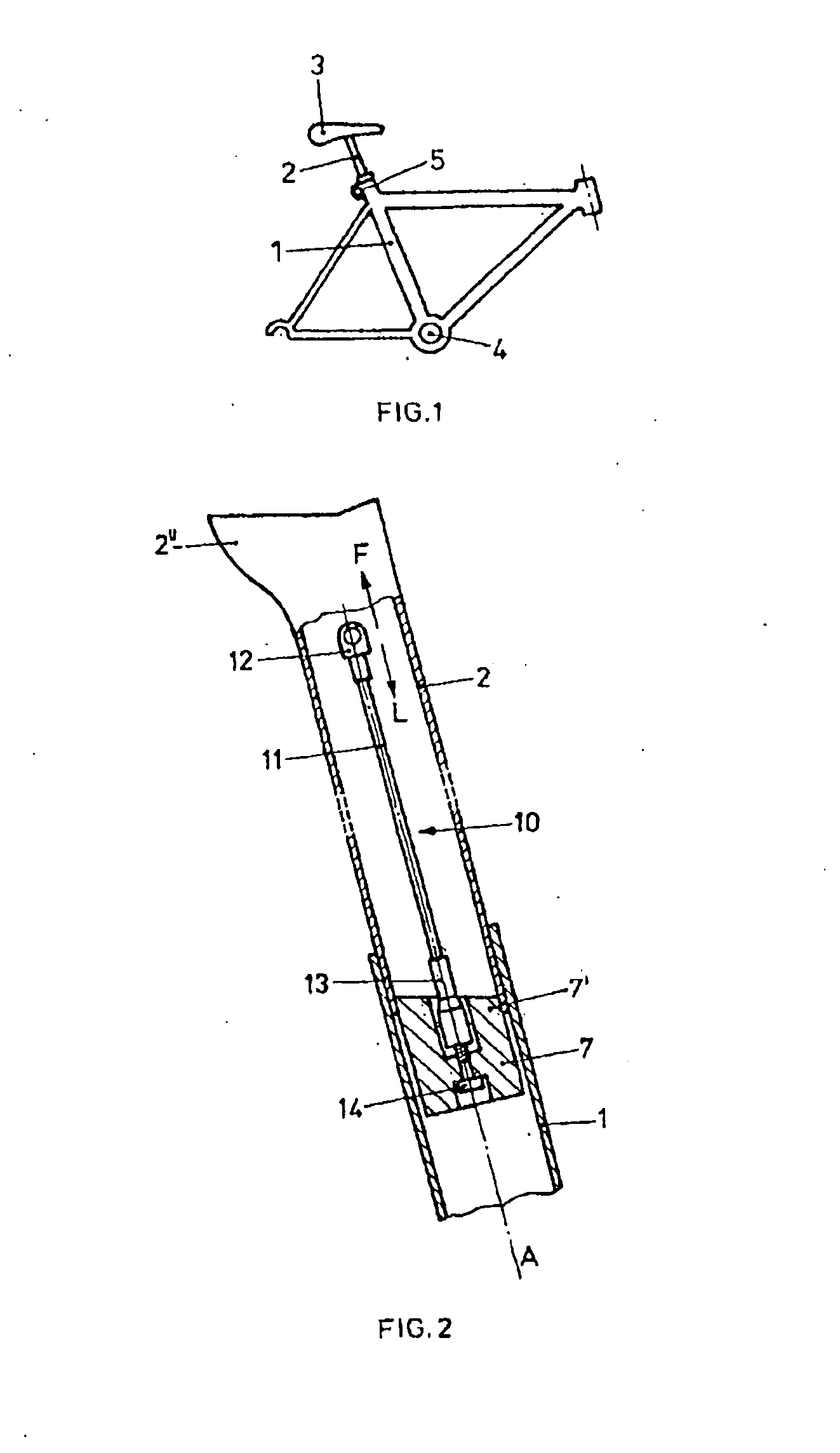
[0031]FIG. 1 shows purely by way of example the view of a conventional bicycle frame, in the central frame tube 1 of which a seat tube 2 is guided in a displaceable manner in the axial direction. A saddle 3 is arranged in a conventional manner, for example adjustable in terms of tilt, on the upper head end of the seat tube 2. The adjustment of the distance of the saddle 3 from the hub 4 of the drive axis of the frame is carried out, as mentioned, by the axial displacement of the seat tube 2 inside the frame tube 1 of the frame. The fixing of the seat tube 2 in the desired position is carried out conventionally, for example, by means of a clamp 5, which acts on the frame tube 1 in the region of its opening for the seat tube 2 and thus reduces the opening cross section and exerts a clamping effect on the seat tube 2.

[0032]FIG. 2 shows diagrammatically the partial longitudinal cross section through a seat tube 2 according to the invention. The lower part of the seat tube 2 is inserted ...


PUM


Abstract

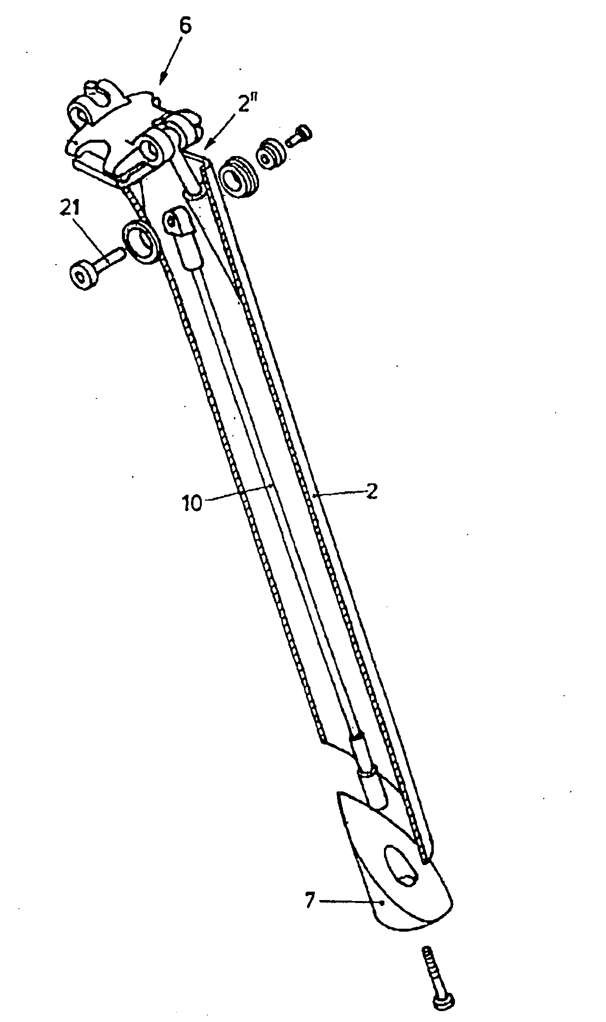
With the present holding device for bicycle saddles with a seat tube (2) that can be inserted into a guide tube (1) of the frame of a bicycle, a saddle carrier (6) arranged at the upper end (2″) of the seat tube (2) as well as a clamping element (7) for fixing the position of the seat tube (2) in the guide tube (1), the clamping element (7) bears against the inner wall of the lower opening of the seat tube (2) at the lower end of the seat tube (2) in a longitudinally displaceable manner and is connected to a tension element (10). The tension element (10) is thereby arranged running in the interior of the seat tube (2) and is connected at its upper end to a holding element (20), wherein the holding element (20) is arranged in the seat tube (2) in a longitudinally displaceable manner with respect to the longitudinal axis (A) of the seat tube (2). The clamping element can thus be easily operated by displacing the holding element (20), which is arranged in the upper region (2″) of the seat tube (2), and a clamping effect between the seat tube (2) and the guide tube (1) from the inside can be achieved. No additional clamping means thus need to be arranged on the outside of the guide tube (1) as well as of the of the seat tube (2).

Description

RELATED APPLICATION[0001]This is a U.S. national phase application under 35 U.S.C. §371 of International Application No. PCT / EP2007 / 063304 filed Dec. 4, 2007.TECHNICAL FIELD[0002]The present invention relates to a holding device for a bicycle saddle with a seat tube that can be inserted into a guide arranged at the upper end of the seat tube as well as a clamping element for fixing the position of the seat tube in the guide tube.BACKGROUND AND SUMMARY[0003]A holding device for a bicycle saddle, also referred to as a support device or seat post, is used for the attachment of the saddle to the frame of the bicycle. Depending on the type of bicycle, different seat posts are known with which the saddle is connected to the frame of the bicycle. Often the relative position of the saddle is thereby embodied to be adjustable with respect to the frame. The saddle can thus be individually adjusted taking into account the body measurements of the respective cyclist with respect to his position...

Claims


Application Information

Patent Timeline
Patent Type & Authority Applications(United States)
IPC IPC(8): B62K19/36
CPCB62J1/08
Inventor SINGENBERGER, ROLFMEILER, RUEDIGASSER, RETO
Owner SINGENBERGER ROLF
Learn More