Rotary wedge scanner

a scanner and wedge-type technology, applied in the field of rotary wedge-type scanners, can solve the problems of reduced attainable speed and accuracy, reduced space requirements, and reduced space requirements, so as to reduce space requirements and the effect of reducing weight and power consumption

Inactive Publication Date: 2010-02-16
EL OP ELECTRO OPTICS INDS
View PDF6 Cites 0 Cited by
  • Summary
  • Abstract
  • Description
  • Claims
  • Application Information

AI Technical Summary

Benefits of technology

[0011]It is thus one of the objects of the present invention to overcome the drawbacks and disadvantages of the known rotary wedge scanners and to provide a scanner that, for a given transmission aperture and angle of deflection, has the lowest possible weight and power consumption and is as compact as possible so as to reduce space requirements.
[0012]It is a further object of the invention to provide a scanner that is capable of operating at high speeds and high accelerations to ensure full flexibility in scanning at a reduced sensitivity to environmental conditions, that does not demand excessive manufacturing tolerances, and in which the friction moment of the bearings, as well as the moment of inertia of the set of rotating components, are both of a minimal value.

Problems solved by technology

This solution, however, is useful only for very small apertures and requires complex electronics.
Yet with increasing optical aperture, attainable speeds and accuracy are reduced.
Also, when large apertures are required, mirror-type scanners need a large space for two mirrors that rotate in planes perpendicular or parallel to one another.
Furthermore, mirrors are very sensitive to environmental conditions in terms of vibrations and temperature fluctuations.
However, the classic wedge-type scanners suffer from serious drawbacks.
With increasing optical aperture, the above-described design becomes very heavy and loses its compactness.
A more serious problem, however, resides in the fact that with increasing bearing diameter, the friction moment of the bearing increases exponentially.
Altogether, larger torque demands not only reduce the service life of the system, but also make control of the wedges more difficult, especially when oscillating movement is required, as well as impairing the reading accuracy of the wedge position.

Method used


Image

  • Rotary wedge scanner
  • Rotary wedge scanner
  • Rotary wedge scanner

Examples


Embodiment Construction

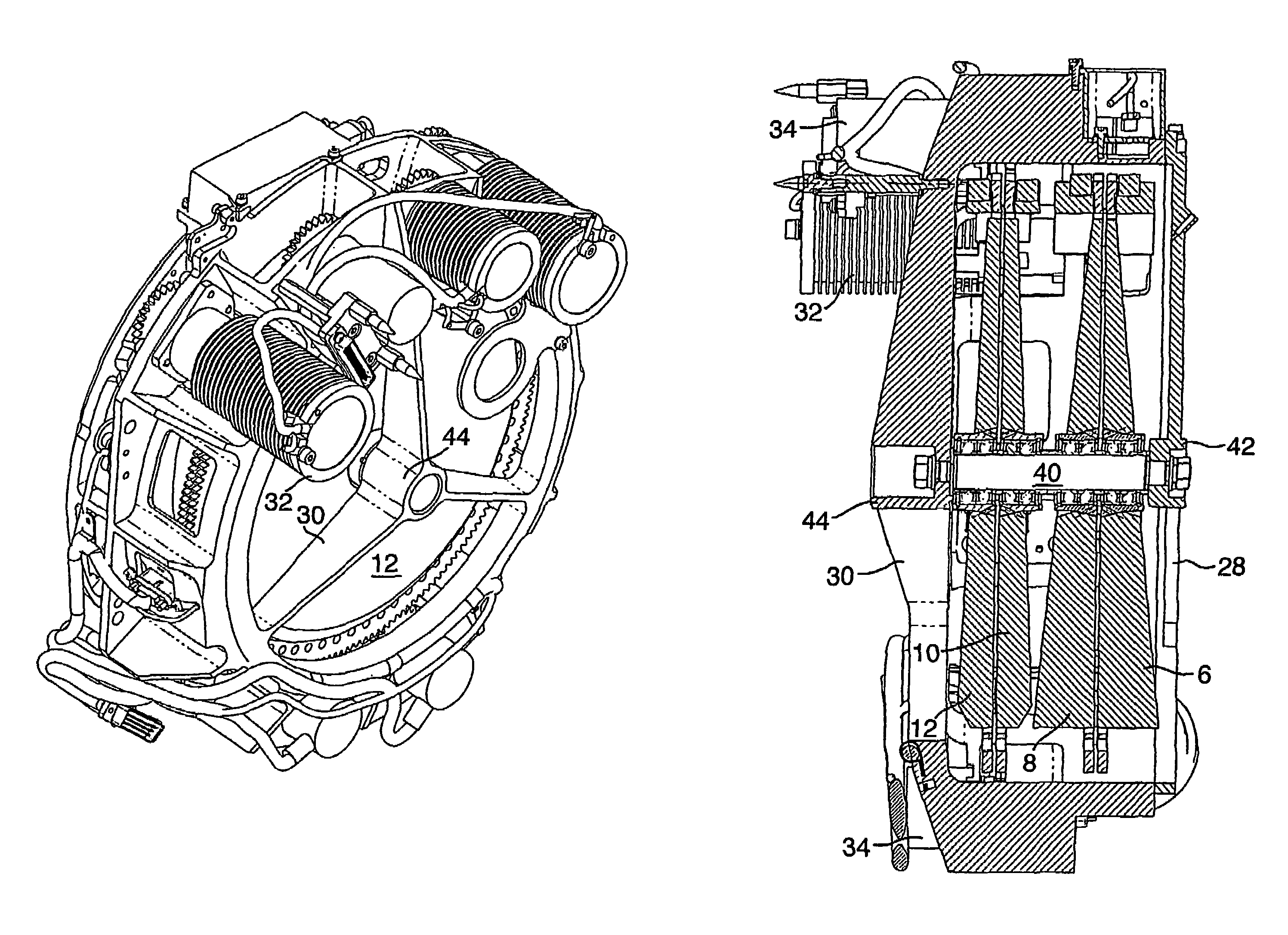
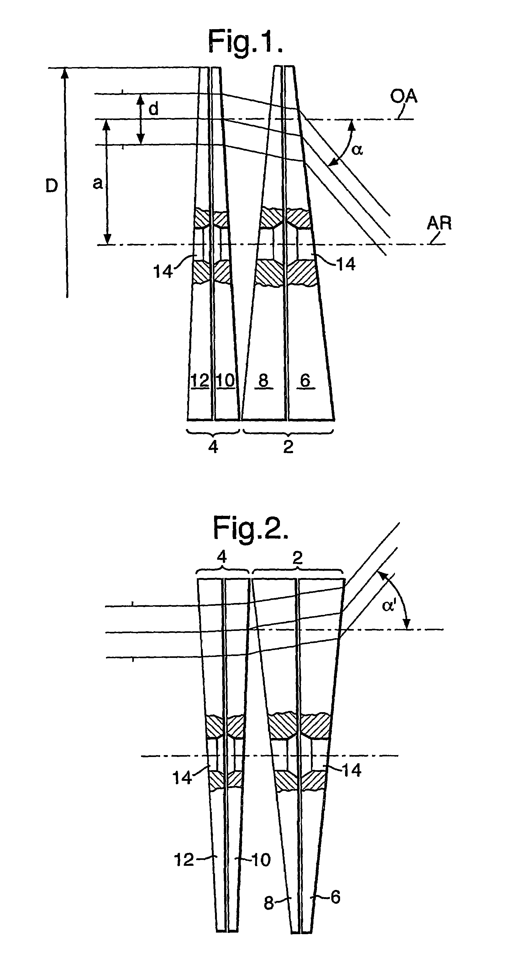
[0026]Referring now to the drawings, there are seen in FIG. 1 two pairs of optical wedges, a front pair of optical wedges 2 comprising two identical wedges and a rear pair of optical wedges 4, also comprising two identical wedges. Wedges 6, 8, 10 and 12 of the two pairs are advantageously made of silicon, because of its relatively high index of refraction. In the illustrated embodiment of the invention, the apex angle of wedges 6 and 8 is 5.9° and the apex angle of wedges 10 and 12 is 2.6°. Other apex angles are possible, as well as other high index of refraction optical materials besides silicon.

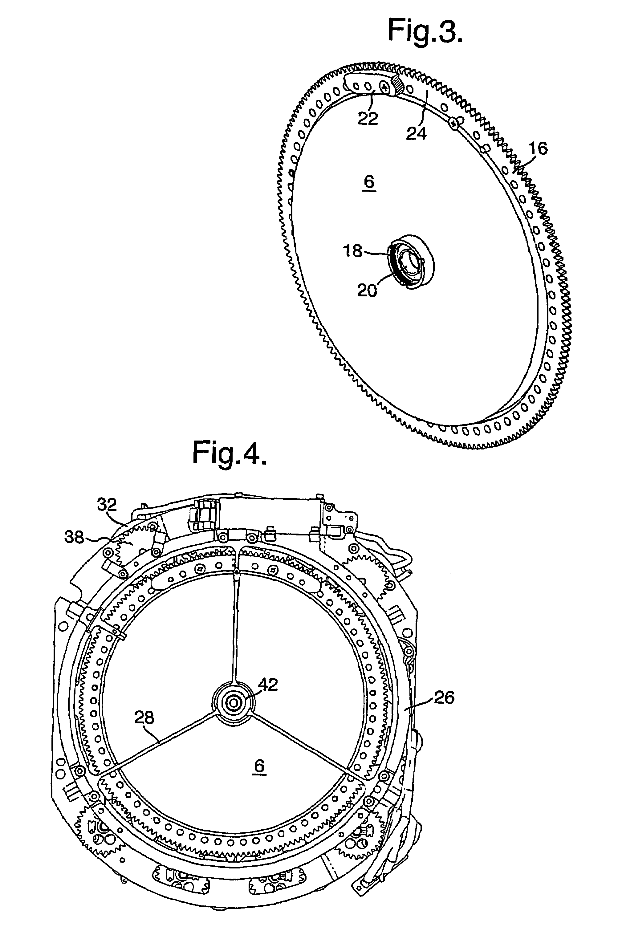
[0027]One of the principal differences between the prior-art wedge scanners and that of the present invention resides in the fact that in the former, the bearings that permit the wedges to rotate are large, peripheral ones, the disadvantages of which have already been discussed above, while the wedges of the scanner of the present invention rotate about small, central bearings. Accordingly,...


PUM


Abstract

A scanning system, including a main housing, and at least one optical wedge (12) rotatable about a shaft means (40) located within the main housing (26), wherein a laser beam having an optical axis and incident on the optical wedge (12), is refracted at least once by the wedge; characterized in that the shaft means (40) passes through the center of the at least one wedge (12) and that the optical axis of the incident laser beam is substantially parallel to, but laterally offset from, the shaft means (40).

Description

FIELD OF THE INVENTION[0001]The present invention relates to a rotary wedge-type scanner, more particularly, to a wedge-type scanner having an optical axis that is laterally offset relative to its mechanical axis.BACKGROUND OF THE INVENTION[0002]Scanners are used in electro-optical devices for target acquisition, obstacle warning systems, range measurement, 3-dimensional profiling, and the like, with the object, e.g., in target acquisition, being “painted” by the controlled laser scanning beam. The laser light reflected from the object is received by the detector section of the device and, after processing, produces a real-time image of the object.[0003]Known solutions for scanning include electro-optical or acousto-optical crystals, the index of refraction of which, and therefore the deflection of the laser beam, can be altered by changing the voltage, respectively the mechanical pressure applied. This solution, however, is useful only for very small apertures and requires complex ...

Claims


Application Information

Patent Timeline
Patent Type & Authority Patents(United States)
IPC IPC(8): G02B26/08G02B7/18G02B26/10
CPCG01J1/04G01J1/0403G01J1/0477G02B7/1805G02B26/0891G02B26/108G02B26/08G02B26/00
Inventor KRUPKIN, VLADIMIRSHCHERANSKI, NAFTALYLUBASHITZ, BOAZ
Owner EL OP ELECTRO OPTICS INDS
Why Eureka
Try Eureka