
Axle device for bicycles

a technology of axial clamping force and spreader device, which is applied in the direction of axle suspension, release mechanism, hub, etc., can solve the problems of high expenditure of force, high axial clamping force fine adjustment, and inability to achieve simultaneous optimal orientation of the clamping lever of the spreader device along the bicycle fork or the bicycle frame, so as to achieve the lowest possible weight and easy operation

Inactive Publication Date: 2015-05-28
LEUENBERGER CHRISTIAN +1
View PDF7 Cites 2 Cited by
  • Summary
  • Abstract
  • Description
  • Claims
  • Application Information

AI Technical Summary

Benefits of technology

The invention is an axle device for bicycles that is simple, lightweight, easy to operate, and can be released and removed from one side. It is less susceptible to dirt accumulation and has the lowest possible weight. The installation process involves inserting the insert element of the retention device into a bicycle fork or frame, passing the tension rod and hollow cylinder through the other passage opening and hub, and engaging the tension rod with the insert element using the quick-action clamping device. The removal process involves opening the quick-action clamping device, releasing the tension rod, and pulling it out with the hollow cylinder. The insert element can be rotated for fine adjustment purposes. The retention device has a securing means to prevent the insert element from falling out when the tension rod is not connected.

Problems solved by technology

A problem with said quick-release axle is that, when inserted with the external thread, it is normally screwed all the way to the end of the external thread flight, and therefore becomes jammed and seizes.
After a certain period of time, the quick-release axle can be removed again only with great difficulty and with high expenditure of force.
Furthermore, fine adjustment of the axial clamping force and simultaneous optimum orientation of the clamping lever of the spreader device along the bicycle fork or the bicycle frame is scarcely possible.
It is also a disadvantage that dirt can easily accumulate in the expanded retention device, which dirt additionally impedes a removal of the axle device because the diameter of the retention device can no longer be readily decreased.

Method used


Image

  • Axle device for bicycles
  • Axle device for bicycles

Examples


Embodiment Construction

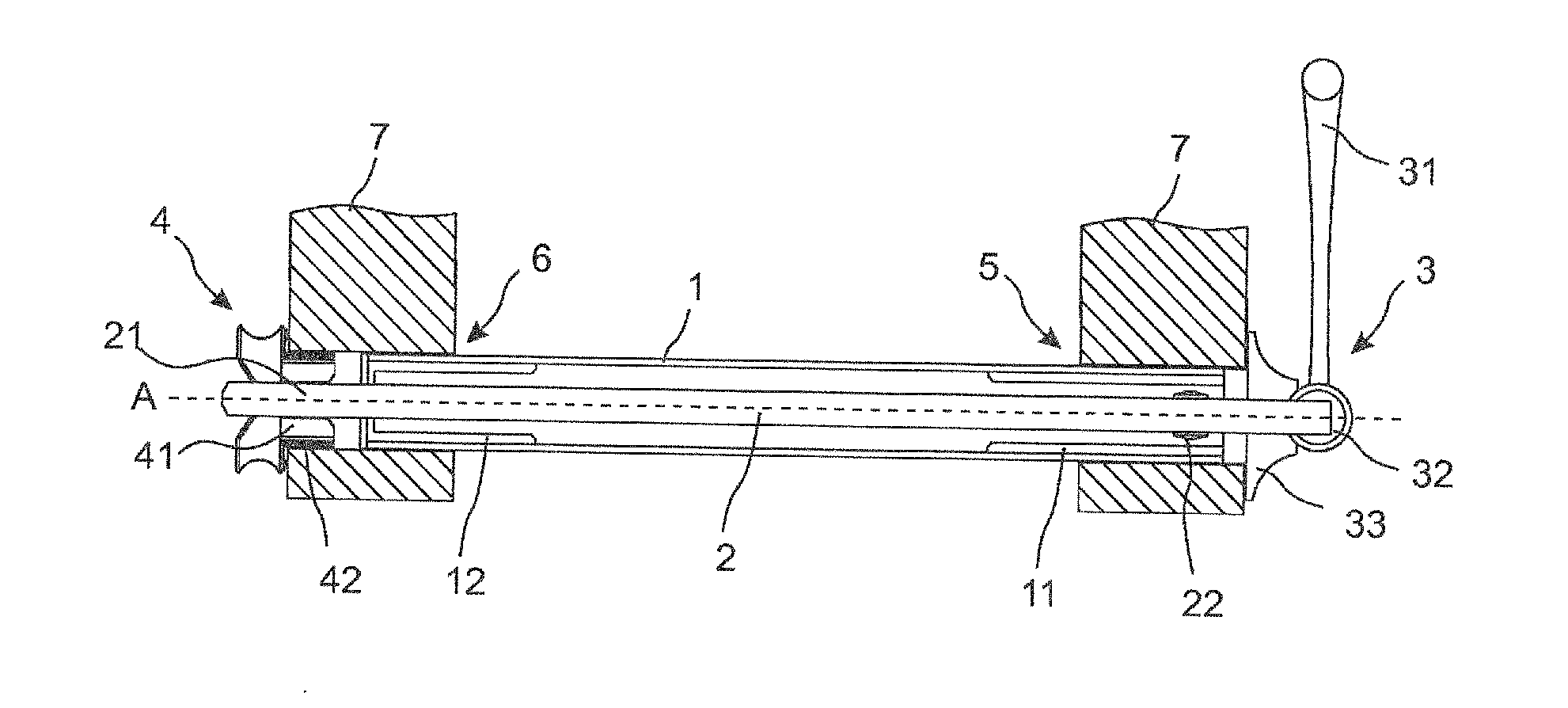
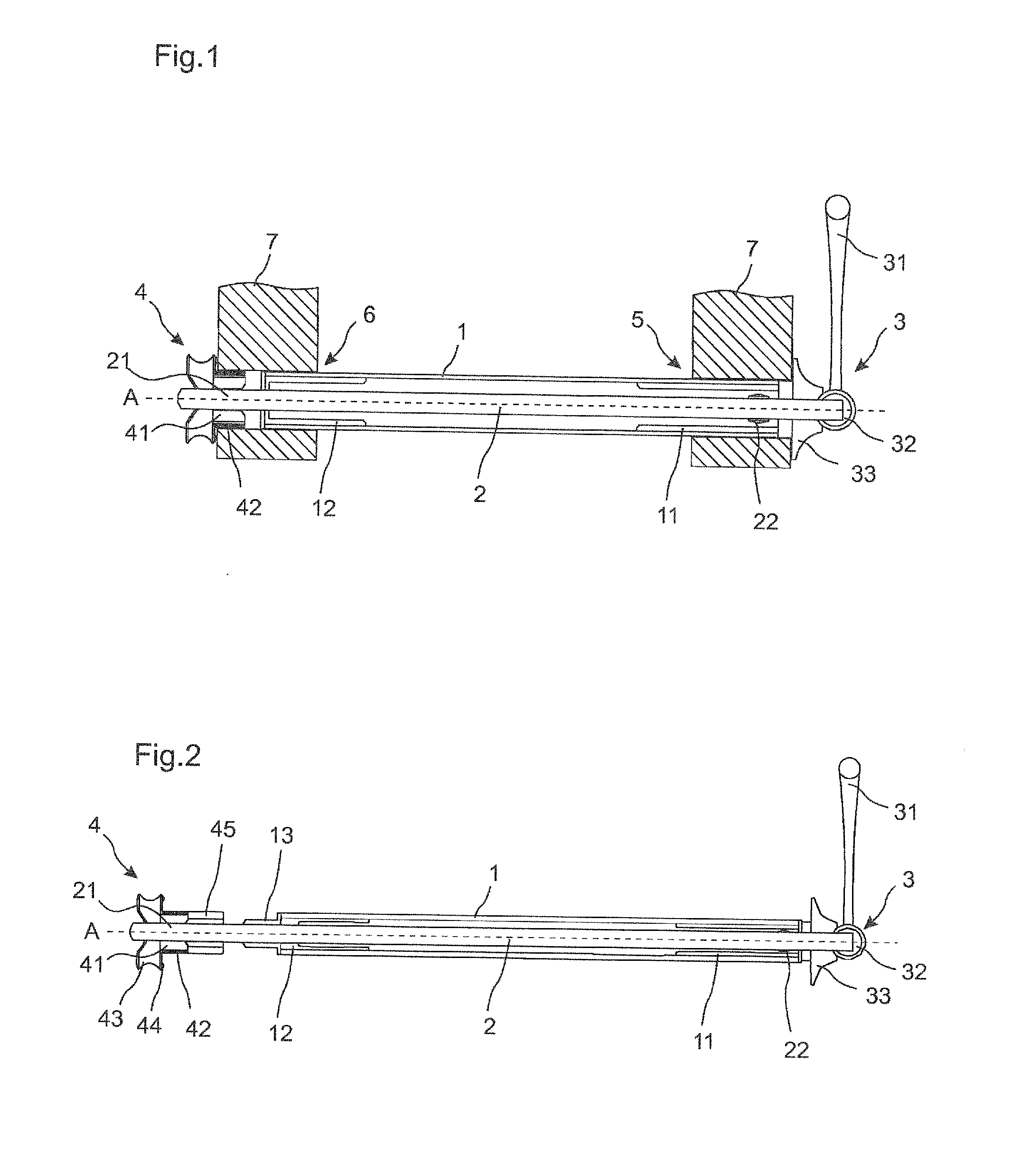
[0027]FIG. 1 shows, in a sectional illustration, an embodiment of an axle device according to the invention for insertion into passage openings 5, 6 of a bicycle fork or of a bicycle frame 7 and for receiving a bicycle hub (not shown). FIG. 1 shows the axle device in the installed state. The axle device comprises a tension rod 2 which extends coaxially along a hollow cylinder 1 and which projects out of the hollow cylinder 1 at both sides. The tension rod 2 and the hollow cylinder 1 are displaceable relative to one another in an axial direction and are rotatable relative to one another about the axis A. On one end of the tension rod 2 there is arranged a quick-action clamping device 3 with a quick-action clamping lever 31, an eccentric 32 and a thrust piece 33, wherein the thrust piece 33 has a larger diameter than the passage openings 5, 6, such that said thrust piece can be brought to bear against the edge of one of the passage openings 5. The other end of the tension rod 2 has a ...


PUM


Abstract

An axle device for inserting into passage openings (5, 6) of a bicycle fork or of a bicycle frame (7) and for accommodating a bicycle hub, comprising a hollow cylinder (1), a tension rod (2) having a quick tensioning device (3), and a retaining device (4), wherein the tension rod (2) extends coaxially along the hollow cylinder (1), and wherein the tension rod (2) and the hollow cylinder (1) can be moved relative to one another and can be rotated about the axis (A). The retaining device (4) comprises an insert element (41) that can be inserted into one of the passage openings (5, 6) such as to be detached from the tension rod (2), and the tension rod (2) has a fastening section (21) at one end, which fastening section can be brought into engagement with the insert element (41) when the axle device is installed.

Description

BACKGROUND OF THE INVENTION[0001]1. Field of the Invention[0002]The invention relates to an axle device for insertion into passage openings of a bicycle fork or of a bicycle frame and for receiving a bicycle hub, comprising a hollow cylinder, a tension rod with a quick-action clamping device, and a retention device, wherein the tension rod extends coaxially along the hollow cylinder, and wherein the tension rod and the hollow cylinder are displaceable relative to one another in an axial direction and are rotatable relative to one another about the axis.[0003]2. Discussion of Related Art[0004]To receive bicycle hubs, bicycle forks and bicycle frames have axle devices which are mounted fixedly on ends of the bicycle fork (front wheel axle) or of the bicycle frame (rear wheel axle). In particular in the case of bicycles that are subjected to high loads, for example mountain bikes, use is often made of quick-release axles. Quick-release axles are passed through the passage openings at t...

Claims


Application Information

Patent Timeline
Patent Type & Authority Applications(United States)
IPC IPC(8): B62K25/02
CPCB62K25/02B62K2206/00B60B27/026
Inventor LEUENBERGER, CHRISTIAN
Owner LEUENBERGER CHRISTIAN
Learn More