
Wheel hub

a hub and wheel technology, applied in the field of hubs, can solve the problems of not being able to race, and not being able to meet the needs of some racing applications, so as to reduce the mass and static weight of the hub, reduce the weight and static weight, and maximize the structural strength

Inactive Publication Date: 2010-12-23
WELD RACING
View PDF10 Cites 8 Cited by
  • Summary
  • Abstract
  • Description
  • Claims
  • Application Information

AI Technical Summary

Benefits of technology

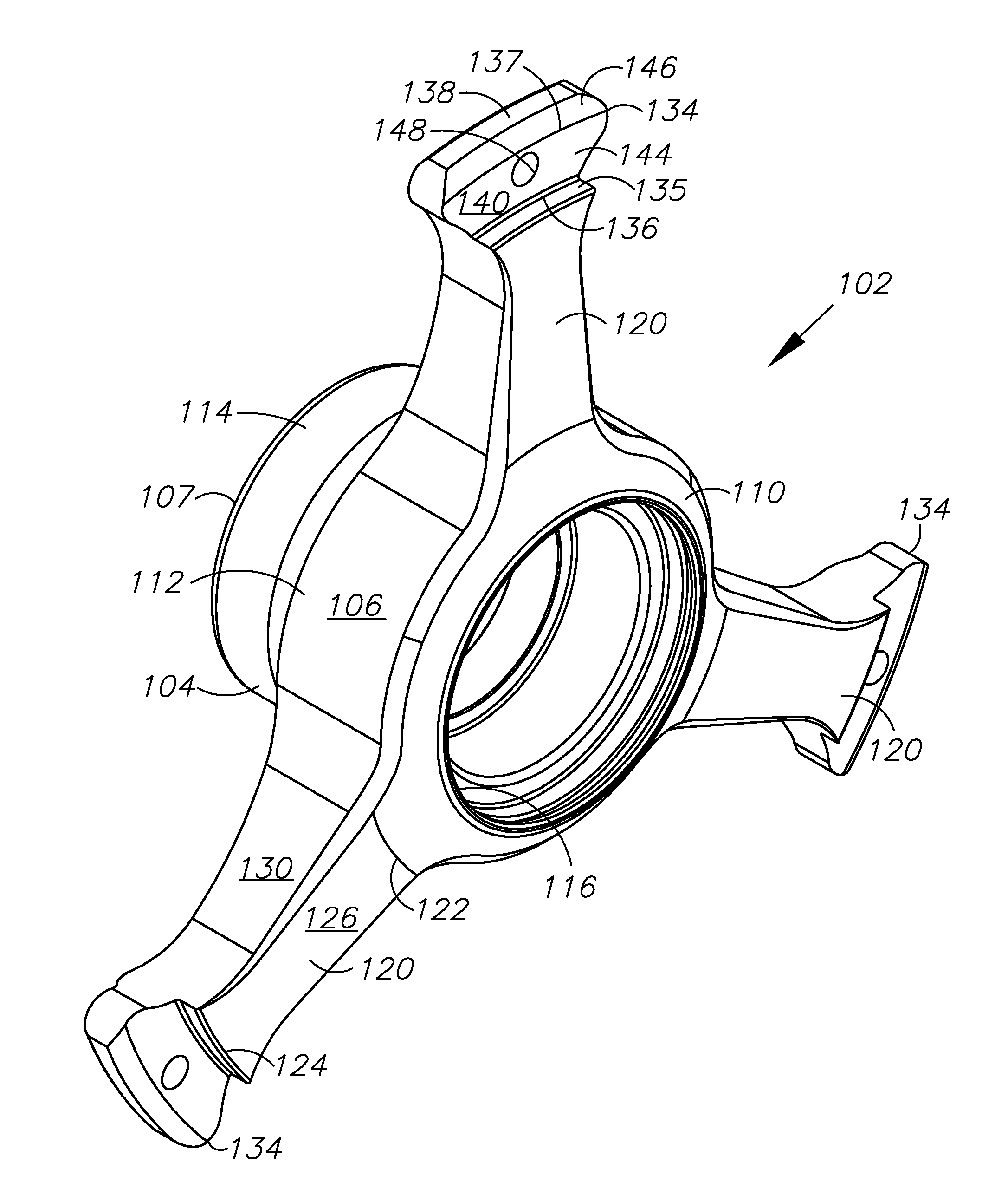
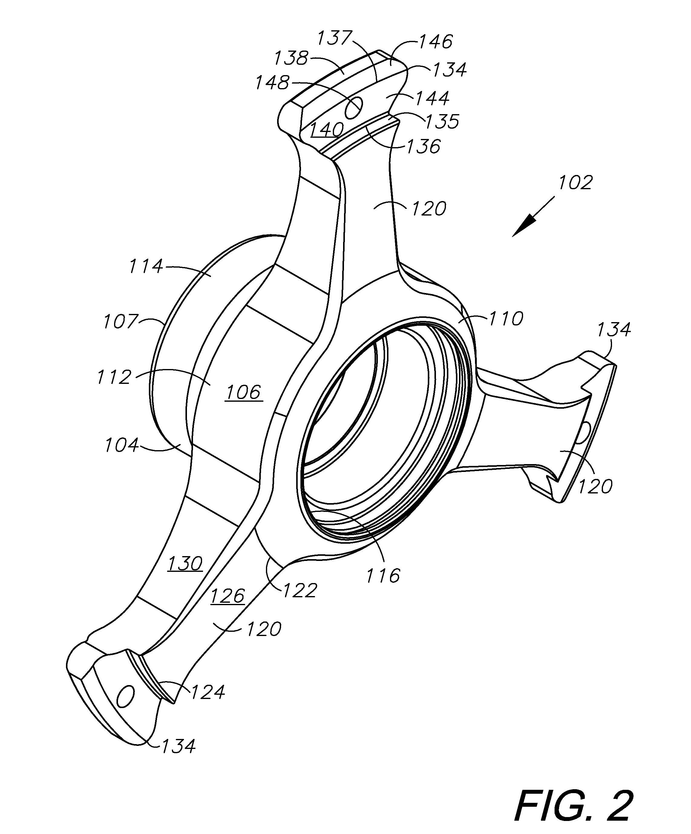
[0011]In a hub embodying the principles of the disclosed subject matter, weight is reduced, and structural strength is maximized by radially-extending arms from a tubular body, and tapering the arms toward a tab that contacts a radial flange on a wheel rim. Such design characteristics of the hub, as well as additional weight-saving attributes, substantially decreases the mass and static weight of the hub thereby reducing the moment of inertia of the hub and wheel.
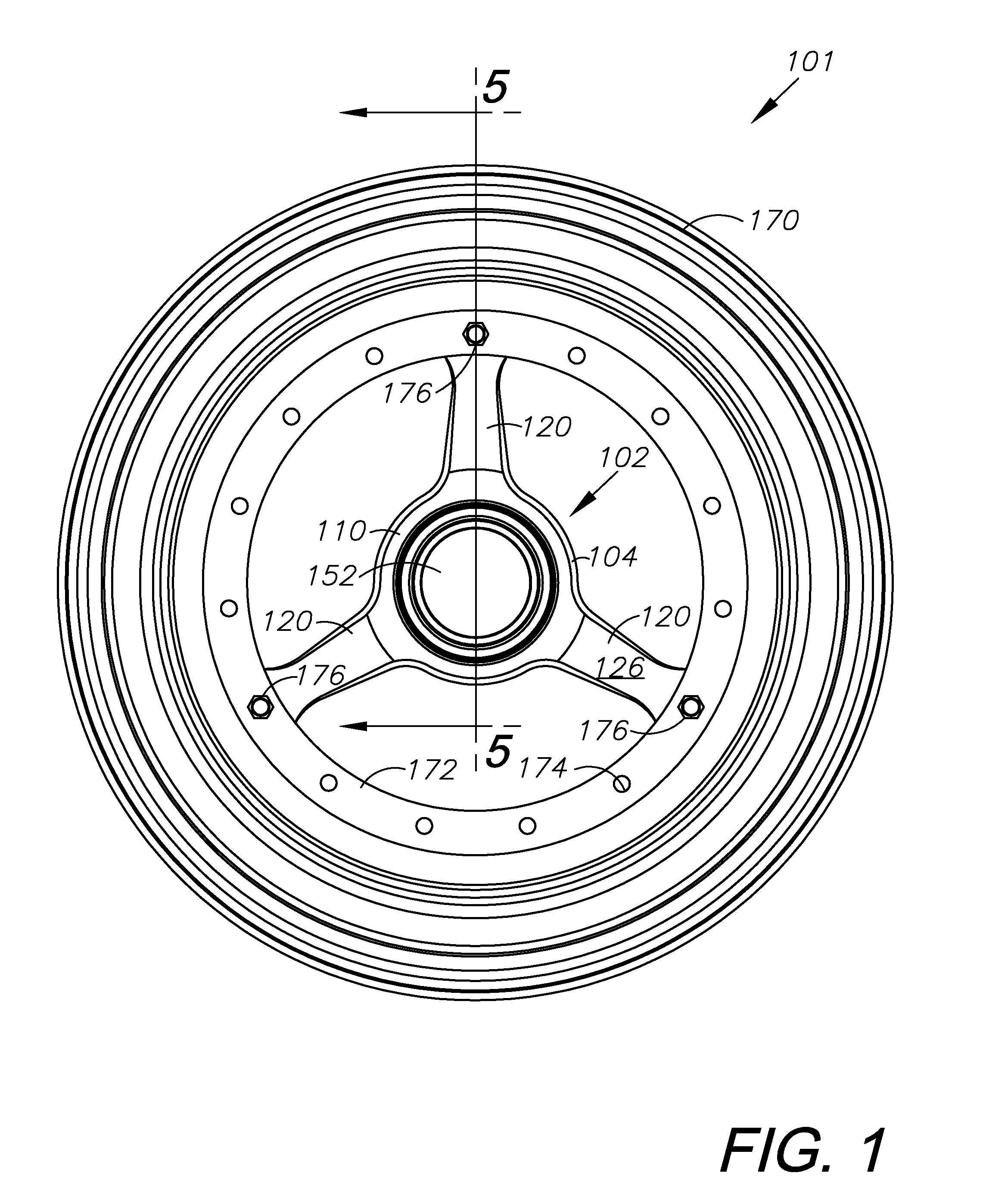
[0013]The hub may be installed on the spindle of the steering mechanism of a vehicle using mounting hardware. Mounting hardware including spacers, gearings, O-rings, and an oil seal are fixed within the bore of the body. The hub is secured to the spindle by a threaded nut and cotter pin. A center cap may be installed over the exposed end of the hub body to prevent dirt and debris from entering the bore of the hub.

Problems solved by technology

Wheels incapable of withstanding the harsh racing environment suffer structural failures that often result in damage to the vehicle as well as damage to surrounding structures or bystanders.
This may not be an option for some racing applications in which the sanctioning body specifies a diameter, or a range of diameters, of the wheels that may be used.
In addition, decreasing the diameter of the wheel may have other disadvantages in applications that rely on the front wheels of the race car to break a photoelectric beam passing in front of the racecar, such as the beam used to count laps or track racing time.
However, decreasing the mass of the wheel requires careful structural analysis of the wheel, the effect it will have on the strength of the wheel, and its ability to withstand racing conditions.

Method used


Image

  • Wheel hub
  • Wheel hub
  • Wheel hub

Examples


Embodiment Construction

[0025]As required, detailed aspects of the disclosed subject matter are disclosed herein; however, it is to be understood that the disclosed aspects are merely exemplary of the invention, which may be embodied in various forms. Therefore, specific structural and functional details disclosed herein are not to be interpreted as limiting, but merely as a basis for the claims and as a representative basis for teaching one skilled in the art how to variously employ the present invention in virtually any appropriately detailed structure.

[0026]Certain terminology will be used in the following description for convenience in reference only and will not be limiting. Said terminology will include the words specifically mentioned, derivatives thereof and words of similar meaning.

[0027]Referring to the drawings in more detail, the reference numeral 102 generally designates an improved wheel hub embodying the principles of the disclosed subject matter having a reduced mass or moment of inertia, a...


PUM


Abstract

A hub for a wheel having a low mass and low moment of inertia includes a tubular body with a bore having, and three radially-extending arms that terminate with a tab. The hub is adapted for mounting on the radial flange of a wheel rim. The arms are space 120 degrees apart and extend from the body tapering from a relatively thick and wide portion to a relatively narrow and thin portion. A bore in the tab receives a fastener for securing the tab to the flange. Mounting hardware including spacers, bearings, O-rings, and an oil seal are secured within the body bore for mounting the hub onto the spindle of a vehicle steering mechanism. A hub nut and cotter pin secures the hub to the spindle. A center cap covers the open end of the body. The hub may optionally include three flanges for mounting a brake rotor.

Description

CROSS-REFERENCE TO RELATED APPLICATIONS[0001]This application claims priority in U.S. Provisional Patent Application No. 61 / 219,643 filed Jun. 23, 2009, which is incorporated herein by reference.BACKGROUND OF THE INVENTION[0002]1. Field of the Invention[0003]The present disclosed technology relates generally to a hub for a wheel. More specifically, the invention provides a wheel hub for use on a wheel in high rotational speed and high torque applications.[0004]2. Description of the Related Art[0005]Wheels used on vehicles subject to high rotational speed and high torque environments, such as sprint racecars, require special wheels that are light weight, strong, and capable of withstanding the harsh racing environment. Racecar builders desire to increase the efficiency of their racecars by decreasing the overall weight of the racecar. It is well known in the automotive industry that components which rotate increase the dynamic load on the racecar, and require more kinetic energy (i.e...

Claims


Application Information

Patent Timeline
IPC IPC(8): B60B27/00B60B3/10
CPCB60B3/10B60B1/08
Inventor RIDER, SCOTT W.
Owner WELD RACING
Learn More