Heat dissipation enhanced LED lamp for spotlight

a technology of led lamps and heat dissipation, applied in the field of electric lamps, can solve the problems of short service life, high temperature, short service life, and short service life, and achieve the effect of high power application of led devices

Inactive Publication Date: 2010-12-23
YU CHIH MING
View PDF11 Cites 27 Cited by
  • Summary
  • Abstract
  • Description
  • Claims
  • Application Information

AI Technical Summary

Problems solved by technology

Although halogen bulbs have advantages of low price, high luminance and soft color temperature, they also have defects such as high power consumption, high temperature, and short service life.
The application of light emitting diodes (LEDs) to light bulbs introduces smaller power consumption and longer service life than conventional light bulbs, but is still hard for commercialization.
The power converter not only requires additional component cost for the LED lamp, but also cannot fit entirely into the standard lamp bases of ordinary light bulbs.
For a LED lamp to be equipped with a power converter, it is necessary to develop special molds to produce containers and corresponding mechanism different from those of ordinary light bulbs to fit the power converter therewithin, which nevertheless increases the cost and volume of the LED lamp.
If the heat is not effectively dissipated, the resulting high temperature will reduce the emissive efficiency and service life of the DC LED device and produce other adverse effects such as wavelength shift.
Moreover, the power converter, particularly the inductor and integrated circuit therein, also generates heat during power conversion, and the consequent high temperature may damage the inductor and integrated circuit and cause failure of the LED lamp accordingly.
The problems caused by insufficient heat dissipation are aggravated especially in high power applications, such as in lighting fixtures for illumination purposes, where the DC LED device generates relatively more heat.
However, low power LED devices are poorly accepted in the market due to their generally low brightness, and these LED lamps tend to have serious light attenuation problems as a result of poor heat dissipation.
An AC LED device, though conveniently applicable in small spaces, still demands heat dissipation.
If a heat dissipating device is added, the resultant LED lamp will be bulky and costly.
However, if no additional assistance is provided to enhance heat dissipation from the AC LED device, the emissive efficiency and service life of the AC LED device will be reduced, wavelength shift is likely to happen, and even worse, the LED epitaxial chip may be burned out.
In addition, the heat sink 104 makes the lamp structure more complex, so that not only mechanism for bonding the heat sink 104 to the lamp base 110 are needed, but also the assembly of the LED lamp 100 becomes more difficult.
Furthermore, in order to match the reflective cups 106 having different apertures or shapes in different applications, the shape and size of the heat sink 104 need to change accordingly, thus increasing the cost and difficulty in production management.

Method used


Image

  • Heat dissipation enhanced LED lamp for spotlight
  • Heat dissipation enhanced LED lamp for spotlight
  • Heat dissipation enhanced LED lamp for spotlight

Examples


first embodiment

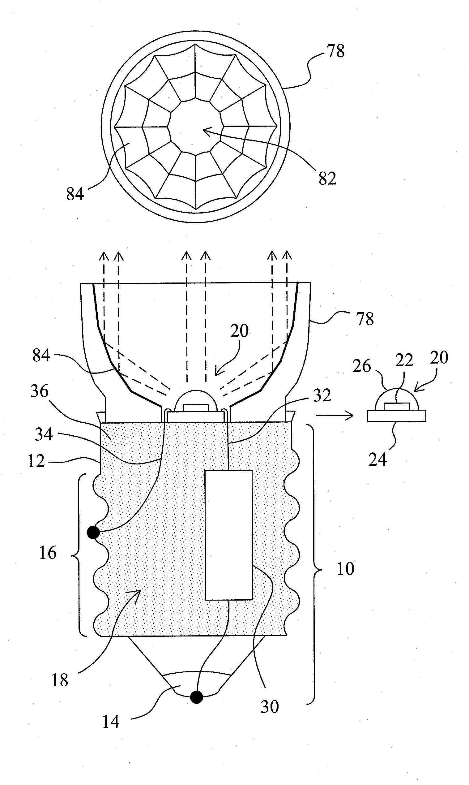
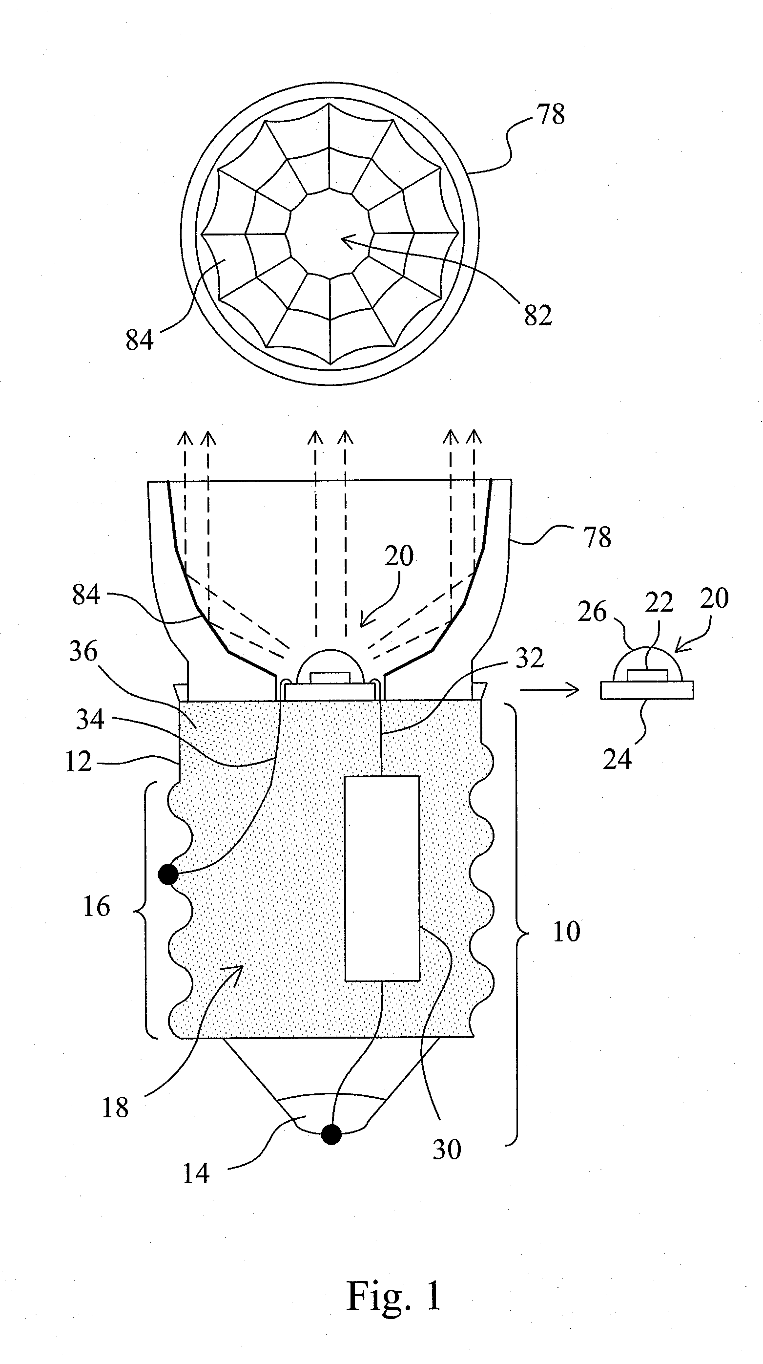
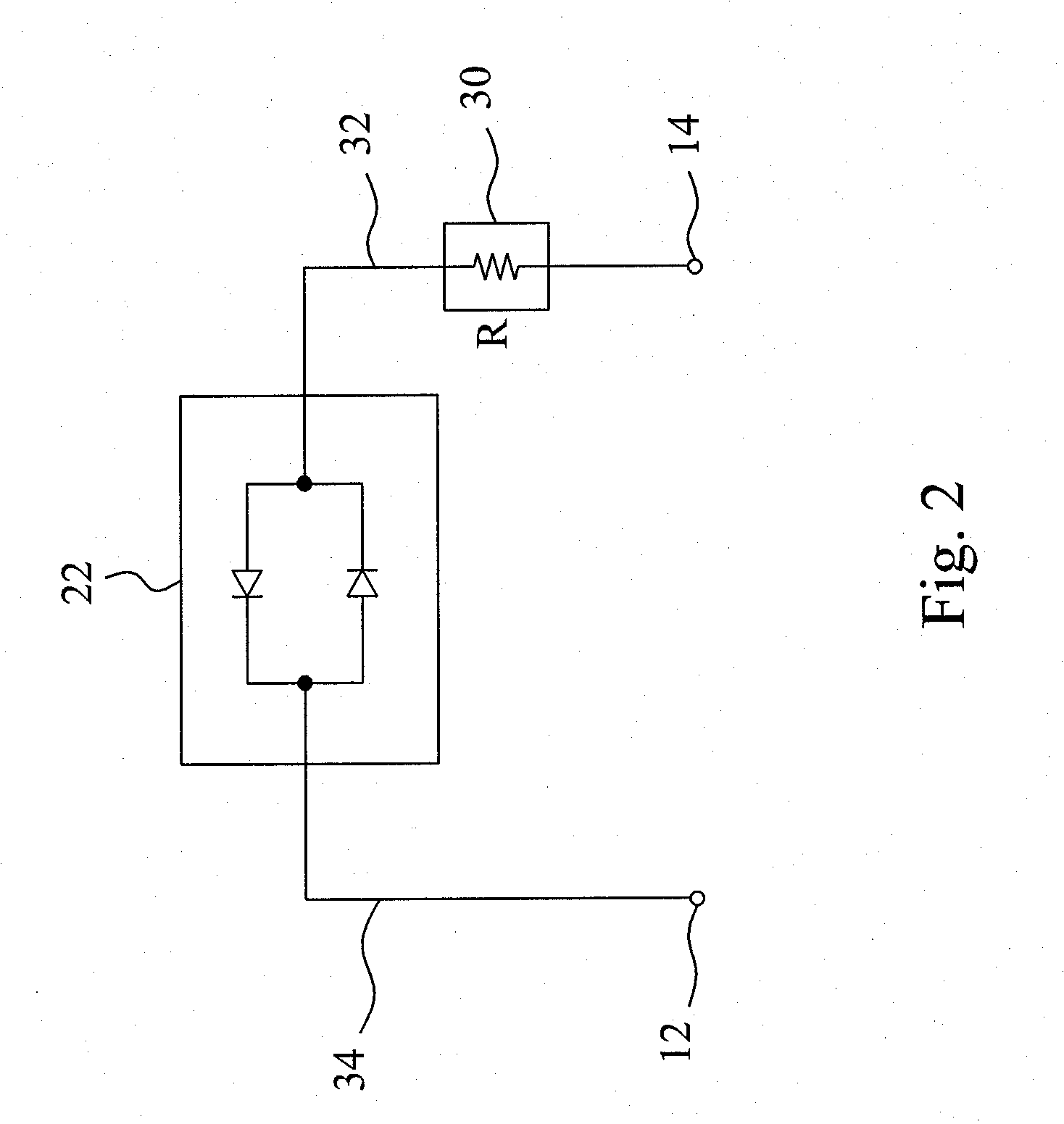
[0022]FIG. 1 is a cross-sectional view of a first embodiment according to the present invention, in which a standard lamp base 10 for use with a small light bulb is used to accentuate the features of heat dissipation enhancement according to the present invention. The lamp base 10 has two electrodes 12 and 14 for receiving an AC power source. As would be understood by a person of ordinary skill in the art, the electrode 12 is a metal housing which has a spiral-threaded configuration 16 and a cavity 18 therein. In this LED lamp, an AC LED device 20 is used as the filament which includes an AC LED epitaxial chip 22 bounded on a leadframe 24 and covered with an encapsulant 26. As the LED packaging is well-known, the package structure of the AC LED device 20 is not detailed in the drawing for the sake of simplicity. A resistor 30 has one end soldered to the electrode 14 and the opposite end connected to a wire 32 that is soldered to the AC LED device 20. Another wire 34 has its two ends...

fourth embodiment

[0029]FIG. 9 is a cross-sectional view of a fourth embodiment according to the present invention, in which the LED filament includes an AC LED device 20 and a thermally conductive member 50 having a dish at its upper end for the AC LED device 20 to be bounded thereon. Preferably, the lower end of the thermally conductive member 50 has a rod or strip shape. The lower end of the thermally conductive member 50 is buried in a thermally conductive electric insulator 36 filled in the cavity 18 of a lamp base 10, so that the thermally conductive electric insulator 36 establishes a heat dissipation channel for the LED filament to an electrode 12 of the lamp base 10. The height of the AC LED device 20 can be adjusted by adjusting the length of the thermally conductive member 50 into the thermally conductive electric insulator 36. Wires 32 and 34 electrically connect the AC LED device 20 to a resistor 30 and the electrode 12 of the lamp base 10, and the resistor 30 is electrically connected t...

fifth embodiment

[0030]FIG. 10 is a cross-sectional view of a fifth embodiment according to the present invention, in which the LED filament includes an AC LED device 20, and the AC LED epitaxial chip 22 of the AC LED device 20 is packaged with chip resistors 90 in a same encapsulant 26. As shown in the right of FIG. 10, the AC LED epitaxial chip 22 and the chip resistors 90 are attached on a pad 88, and bounding wires 92 and 94 are used to electrically connect the AC LED epitaxial chip 22 to the chip resistors 90 and the chip resistors 90 to the pins 66, whose equivalent circuit is also shown in the drawing. The AC LED device 20 is attached on a thermally conductive electric insulator 36 filled in the cavity 18 of a lamp base 10, and has its pins 66 electrically connected to the electrodes 12 and 14 of the lamp base 10, respectively. In this embodiment, fewer components are used and thus simplify the assembly process of the LED lamp.

[0031]In the above embodiments, depending on practice applications...


PUM

PropertyMeasurementUnit
rated poweraaaaaaaaaa
resistanceaaaaaaaaaa
rated poweraaaaaaaaaa

Abstract

In a LED lamp, a thermally conductive electric insulator is filled in a cavity of a lamp base, a LED filament includes an AC LED device, a resistor is connected with the AC LED device in series between two electrodes of the lamp base to form an electric loop, and a reflective cup has a hole at a bottom thereof to expose the AC LED device and a reflective surface to reflect light of the AC LED device for providing a spotlight. The thermally conductive electric insulator mechanically contacts the LED filament and the first one of the two electrodes, and thereby establishes a heat dissipation channel from the AC LED device to the first electrode therethrough.

Description

CROSS REFERENCE TO RELATED APPLICATION[0001]This application is a continuation-in-part of U.S. patent application Sera No. 12 / 457,718, filed Jun. 19, 2009 and entitled “Heat Dissipation Enhanced LED Lamp,” the disclosure of which is hereby incorporated by reference as if set forth fully herein.FIELD OF THE INVENTION[0002]The present invention is related generally to electric lamps and, more particularly, to a LED lamp for spotlight.BACKGROUND OF THE INVENTION[0003]Light bulbs can be classified into illumination lamps and decoration lamps according to their applications. The spotlight bulb is one of decoration lamps. Different from the wide-range and uniform light irradiation provided by an illumination lamp, a lamp for spotlight simply focuses its light within a narrow area. Currently, most of lamps for spotlight use halogen bulbs. Although halogen bulbs have advantages of low price, high luminance and soft color temperature, they also have defects such as high power consumption, hi...

Claims


Application Information

Patent Timeline
Patent Type & Authority Applications(United States)
IPC IPC(8): H01J61/52
CPCF21Y2101/02F21V29/004F21V23/004F21V7/048F21V7/22F21K9/1375F21K9/23F21K9/238F21V7/24F21V7/28F21V23/006F21V29/71F21Y2115/10
Inventor YU, CHIH-MING
Owner YU CHIH MING
Why Eureka
Try Eureka