Touch screen and touch module

a technology of optical touch and touch screen, which is applied in the direction of instruments, computing, electric digital data processing, etc., can solve the problems of increasing assembly complexity, increasing assembly cost, and not satisfying the user's requirement to control the operating platform and objects, and achieves low failure rate and simple structure.

Inactive Publication Date: 2010-12-23
SONIX TECH
View PDF5 Cites 42 Cited by
  • Summary
  • Abstract
  • Description
  • Claims
  • Application Information

AI Technical Summary

Benefits of technology

[0006]An embodiment of the present invention provides a touch module of which a structure is simple and has low failure rate.
[0007]An embodiment of the present invention provides a touch screen having low failure rate.
[0015]In an embodiment of the present invention, the number of the touch objects, for example, is two. When the touch objects are simultaneously located in the sensing space in at least one of the unit times, the touch images sensed by the first image sensor, the second image sensor, the third image sensor, and the fourth image sensor each have at least one reflex point, and the touch images sensed by at least two of the first image sensor, the second image sensor, the third image sensor, and the fourth image sensor each have two reflex points in the unit times. The control unit is adapted to compare positions of the reflex points in the touch images to eliminate the positions of the touch objects relative to the displaying surface which do not exist and determine the positions of the touch objects relative to the displaying surface.
[0025]In the touch screen and the touch module in the embodiments of the present invention, the image sensor is used to capture the bright spot, i.e. the light beam reflected by the touch object. Compared with the touch module in which capturing a dark spot, i.e. a light shading spot, is adopted, and a good back light source is formed by disposing reflecting bars and light emitting bars on edges of the displaying surface, the structures of the touch screen and the touch module in the embodiments of the present invention are simpler. Accordingly, it can reduce cost of the touch screen and the touch module, and the touch screen is beautiful.
[0026]Moreover, the light sources are controlled to stay at the ON state by turns in the touch module and the touch screen in the embodiments of the present invention. Accordingly, it is avoided that the image sensors are interfered with light beams emitted by unnecessary light sources. Therefore, the touch module and the touch screen in the embodiments of the present invention have low failure rate.

Problems solved by technology

With the development of optoelectronic technology, it can not satisfy a user's requirement to control the operating platform and objects in the screen by using a mouse.
However, the touch film adhered to the panel and the tiny touch device integrated in the panel both affect light transmittance of the LCDs.
The back light source is provided by adhering reflecting bars and light emitting bars to edges of the displaying surface of the screen, but it may simultaneously increase complexity and cost of assembly.
Furthermore, it is easily affected by environment light beams to capture the dark spots.

Method used


Image

  • Touch screen and touch module
  • Touch screen and touch module
  • Touch screen and touch module

Examples


Embodiment Construction

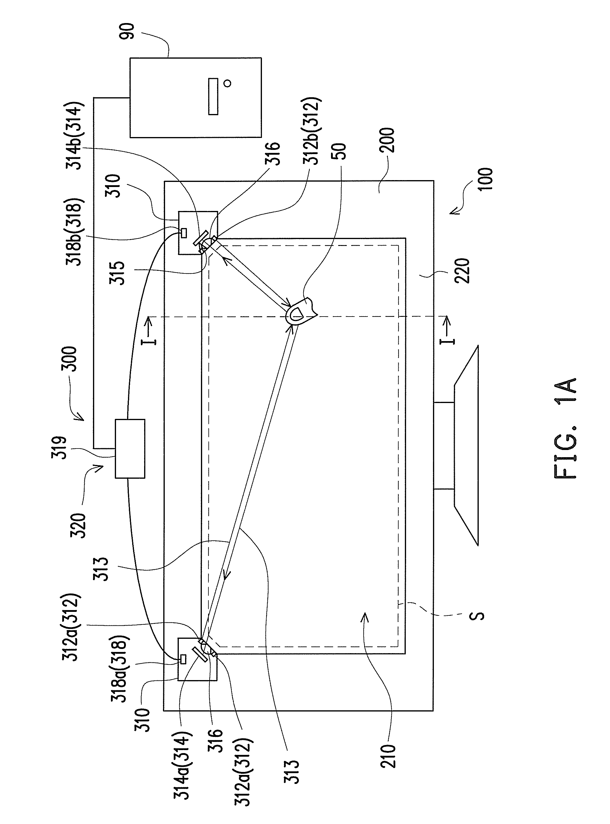
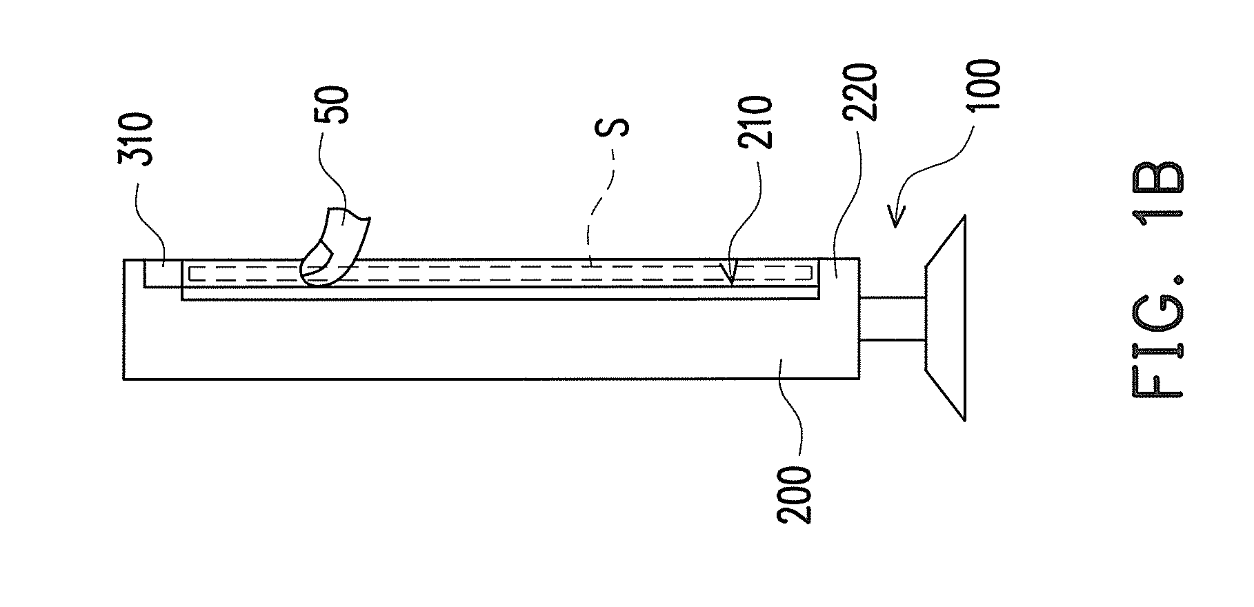
[0047]FIG. 1A is a front view of a touch screen and an operating platform according to an embodiment of the present invention. FIG. 1B is a schematic cross-sectional view of the touch screen in FIG. 1A along line I-I. FIG. 1C is an enlarged view of touch units in FIG. 1A. Referring to FIG. 1A, FIG. 1B, and FIG. 1C, the touch screen 100 of the present embodiment includes a display 200, at least two touch units 310, and a control unit 320. In the present embodiment, the touch units 310 and control unit 320 may compose of a touch module 300. The display 200 has a displaying surface 210. In the present embodiment, the touch units 310 is disposed beside the displaying surface 210, and each of the touch units 310 includes at least one light source 312 and an image sensor 314. In FIG. 1A, the number of the light sources 312, for example, is two. In other words, in the present embodiment, the touch module 300 includes at least one light source 312, a first image sensor 314a, a second image ...


PUM


Abstract

A touch screen including a display, at least two touch units and a control unit is provided. The display has a displaying surface. The touch units are disposed beside the displaying surface. Each of the touch units includes a light source and an image sensor. The light source is adapted to emit a light beam toward a sensible space in front of the displaying surface. The image sensor is adapted to capture the bright spot in the sensible space, and generate an image signal. The control unit is electrically connected to the light sources and the image sensors. The control unit is adapted to receive the image signals from the image sensors, and determine the position of the bright spot relative to the displaying surface according to the image signals. A touch module and a control method are also provided.

Description

CROSS-REFERENCE TO RELATED APPLICATION[0001]This application claims the priority benefit of Taiwan application serial no. 98120875, filed on Jun. 22, 2009. The entirety of the above-mentioned patent application is hereby incorporated by reference herein and made a part of specification.BACKGROUND OF THE INVENTION[0002]1. Field of the Invention[0003]The present invention generally relates to a touch module and a touch screen, and more particularly, to an optical touch module and an optical touch screen.[0004]2. Description of Related Art[0005]With the development of optoelectronic technology, it can not satisfy a user's requirement to control the operating platform and objects in the screen by using a mouse. Accordingly, an interface more humanistic than the mouse is gradually developed. In these humanistic interfaces, the touch method by using fingers is closest to human experience in the daily life. Accordingly, elders and children may not use the mouse, but they can touch with fin...

Claims


Application Information

Patent Timeline
Patent Type & Authority Applications(United States)
IPC IPC(8): G06F3/041
CPCG06F3/0421
Inventor LEE, CHI-FENGTUNG, PEI-HUI
Owner SONIX TECH
Why Eureka
Try Eureka