Projection type image display
- Summary
- Abstract
- Description
- Claims
- Application Information
AI Technical Summary
Benefits of technology
Problems solved by technology
Method used
Image

Examples
embodiment 1
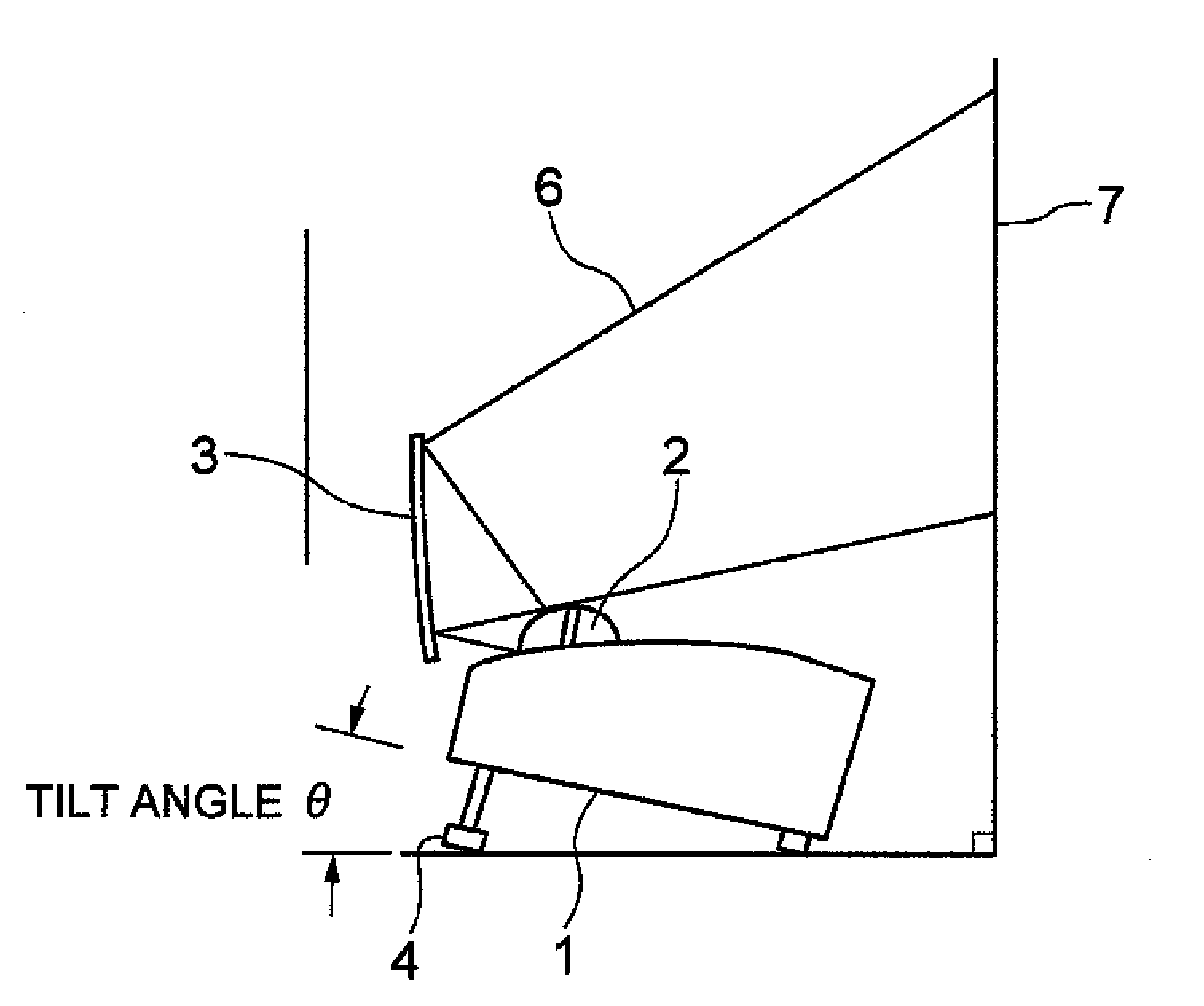
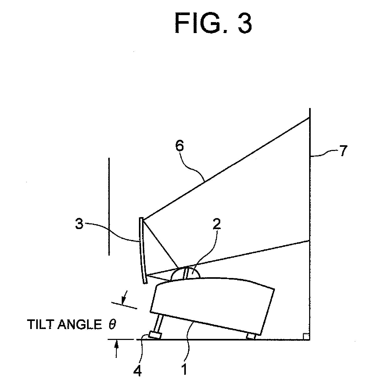
[0043]Next, a structure capable of achieving a tilt angle of the projection type image display apparatus 1 when the reflection mode is set will now be described more concretely.
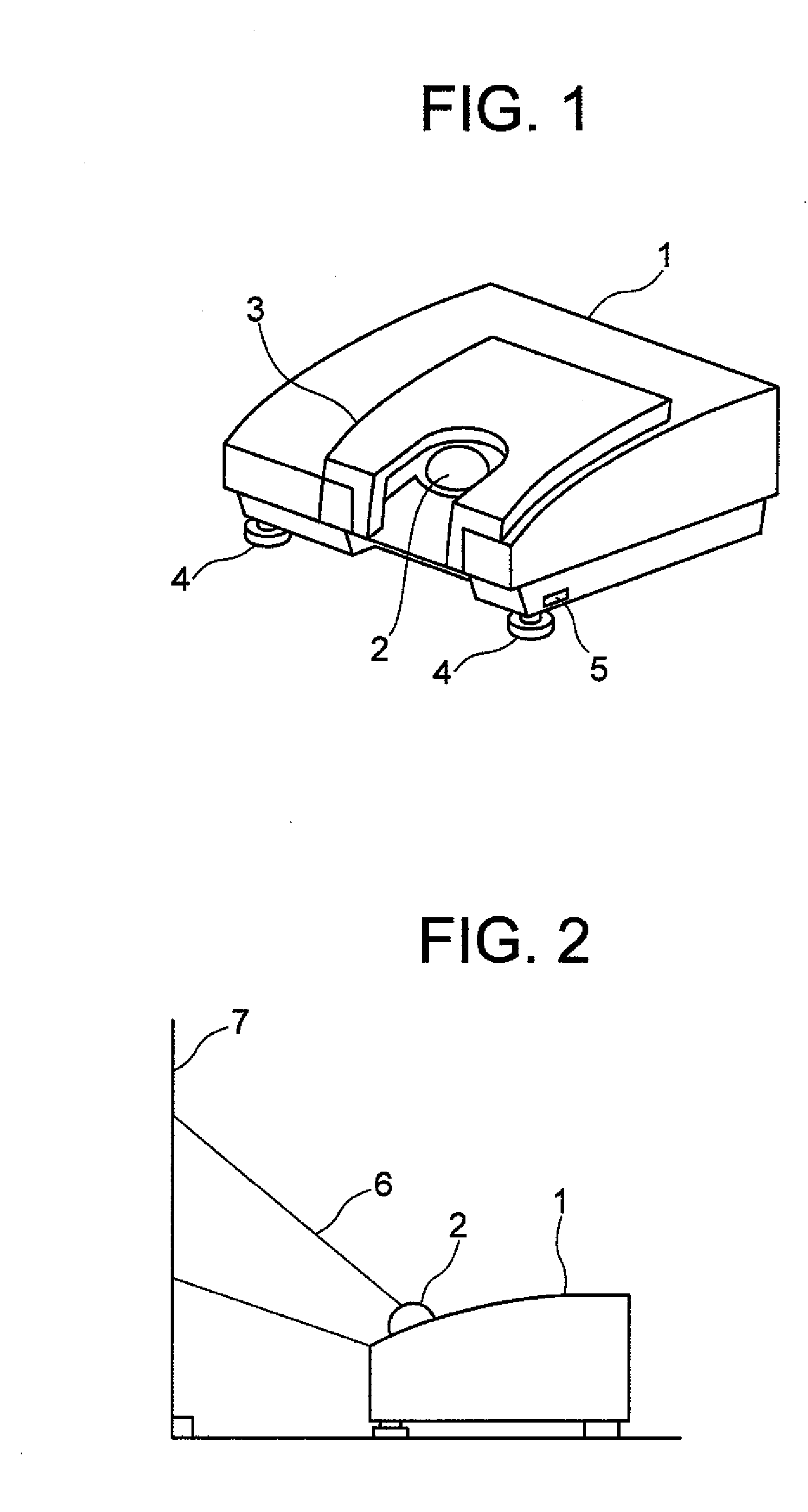
[0044]FIG. 6, FIG. 7 and FIG. 8 are views for illustrating the structure of the adjustment leg 4 of FIG. 1 in detail. Since the function of the adjustment leg 4 has already been described, the explanation thereof is omitted and the structure of the adjustment leg 4 will now be described.
[0045]The adjustment leg 4 is constructed by employing a leg portion 8 which is contacted to a setting plane of the bottom portion of the projection type image display apparatus 1; a shaft portion 9 having a screw groove; and a stopping spring 10 which is provided at an end portion located opposite to the leg portion 8 of the shaft portion 9. The adjustment leg 4 has been mounted on a case boss portion 12 in a slidable manner. The sliding operation of the shaft portion 9 is stopped by fitting the screw groove of the shaft port...
embodiment 2
[0049]It will be described a structure capable of achieving a tilt angle of the projection type image display apparatus 1 when the reflection mode is set, as another embodiment (Embodiment 2) with reference to FIG. 9 and FIG. 10. FIG. 9, FIG. 10, and FIG. 11A to FIG. 11D are views of the structure of the adjustment leg 4 of FIG. 1 in detail. Since the function of the adjustment leg 4 is described as above, the explanation thereof is omitted, and the structure of the adjustment leg 4 will now be described.
[0050]It should be understood that this Embodiment 2 has a difference that a stopping spring 10 is different from that of the above-explained Embodiment 1.
[0051]The adjustment leg 4 is constructed by employing a leg portion 8 which is contacted to the setting plane of the bottom portion of the projection type image display apparatus 1, a shaft portion 9 having a screw groove, and a stopping spring 10 which is provided at an end portion located opposite to the leg portion 8 of the sh...
embodiment 3
[0057]It will be described a structure capable of achieving a tilt angle of the projection type image display apparatus 1 when the reflection mode is set as another embodiment with reference to FIG. 12 and FIG. 13.
[0058]In Embodiment 3, instead of the above-described adjustment legs 4 of Embodiment 1, a tilt angle of the projection type image display apparatus 1 is achieved by tilt leg portions 13 provided on a reflection mirror 3.
[0059]FIG. 12 is a view for showing an outer appearance when the projection type image display apparatus 1 is operated in the direct projection mode. FIG. 13 is a view for indicating an outer appearance when the projection type image display apparatus 1 is operated in the reflection mode. The tilt leg portions 13 capable of achieving the tilt angle of the projection type image display apparatus 1 is provided on the reflection mirror 3. Since, by providing the tilt leg portions 13 on the reflection mirror 3, the projection type image display apparatus 1 can...
PUM
 Abstract
Description
Claims
Application Information
 - Generate Ideas
- Intellectual Property
- Life Sciences
- Materials
- Tech Scout
- Unparalleled Data Quality
- Higher Quality Content
- 60% Fewer Hallucinations
Browse by: Latest US Patents, China's latest patents, Technical Efficacy Thesaurus, Application Domain, Technology Topic, Popular Technical Reports.
© 2025 PatSnap. All rights reserved.Legal|Privacy policy|Modern Slavery Act Transparency Statement|Sitemap|About US| Contact US: help@patsnap.com