Providing cloud-based services using dynamic network virtualization

a network virtualization and cloud-based technology, applied in data switching networks, instruments, program control, etc., can solve the problems of indefinite transition period and only support of vm migration techniques, and achieve the effect of faster service provisioning and network support for new applications

Active Publication Date: 2010-12-23
ALCATEL LUCENT SAS
View PDF6 Cites 618 Cited by
  • Summary
  • Abstract
  • Description
  • Claims
  • Application Information

AI Technical Summary

Benefits of technology

[0007]Embodiments of the invention provide a cloud-based service over a system that has a dynamic network virtualization architecture. The architecture includes a set of distributed forwarding elements with centralized control, and at least one virtual machine that is bound to one of the forwarding elements. These features enable the VM to be migr...

Problems solved by technology

However, typical VM migration techniques currently only support migration in the same local area network (LAN).
However, a limitation of this approach is that the duration of the tran...

Method used


Image

  • Providing cloud-based services using dynamic network virtualization
  • Providing cloud-based services using dynamic network virtualization
  • Providing cloud-based services using dynamic network virtualization

Examples


Embodiment Construction

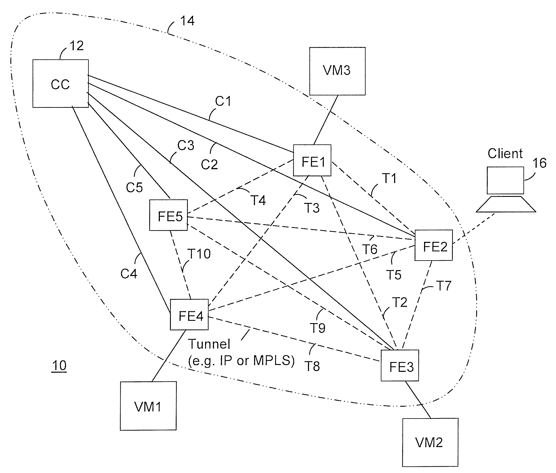
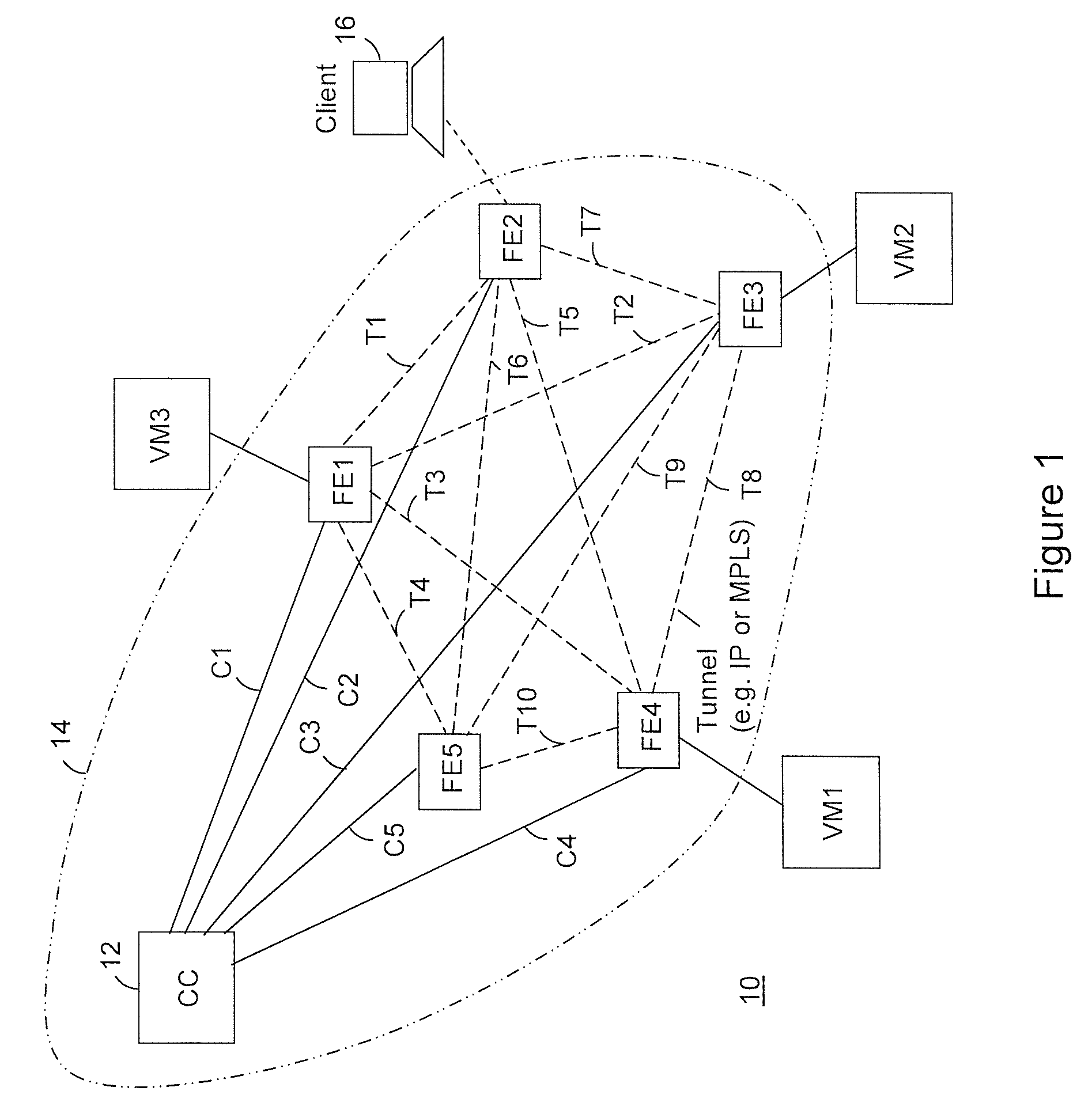
[0020]Referring to FIG. 1, a system 10 for providing cloud-based services using dynamic network virtualization includes a cluster of forwarding elements (FEs) FE1-FE5 and one or more centralized controllers (CC) 12. The CC 12 has a respective control connection C1 to C5 to each forwarding element FE1-FE5. The forwarding element FE1-FE5 handle data plane functions such as packet forwarding, policing and policy enforcement. The forwarding element FE1-FE5 also set up a virtual backplane between each other as necessary. For example a fully meshed network of tunnels T1 to T10, e.g. IP or MPLS shown in FIG. 1 in dotted line, form the virtual backplane. Although a full mesh of tunnels is shown, it should be appreciated that such a full mesh is not a requirement. The system 10 includes a plurality of virtual machines VM1-VM3, each of which is bound to a respective forwarding element FE1-FE5. For example, a first forwarding element FE1 is bound to a third virtual machine VM3, a third forward...


PUM


Abstract

The invention is directed to providing cloud-based services using dynamic network virtualization. Embodiments of the invention provide a cloud-based service over a system that has a dynamic network virtualization architecture. The architecture includes a set of distributed forwarding elements with centralized control, and at least one virtual machine that is bound to one of the forwarding elements. These features enable the virtual machine to be migrated across a wide area network while maintaining its original IP address and service continuity.

Description

FIELD OF THE INVENTION [0001]The invention is directed to packet switching communication networks, particularly to providing services according to a cloud-computing paradigm in which applications are hosted by virtual machines (VM) in interconnected data centers.BACKGROUND OF THE INVENTION [0002]It is envisaged that services and applications will migrate to a cloud-computing paradigm where thin-clients on user-devices access, over a packet switched network, applications hosted in data centers by application service providers. Examples include Software as a Service (SaaS) applications, cloud-based gaming applications and cloud-supported virtual desktops. For good performance and efficiency, it is desirable to deliver these services from certain locations, which are dependent on a current set of users. Typically, this set of users is continually changing; hence such locations are likewise dynamic in their nature.[0003]To accommodate the need to deliver cloud-based services from a dyna...

Claims


Application Information

Patent Timeline
IPC IPC(8): H04L12/56H04L45/02
CPCG06F9/45558G06F2009/4557H04L67/10H04L45/02H04L45/00G06F2009/45595H04L49/70
Inventor HAO, FANGLAKSHMAN, T.V.MUKHERJEE, SARITSONG, HAOYU
Owner ALCATEL LUCENT SAS
Why Eureka
Try Eureka