Cyclone-like separator for a vacuum cleaner

Inactive Publication Date: 2010-12-30
AB ELECTROLUX
View PDF2 Cites 8 Cited by
  • Summary
  • Abstract
  • Description
  • Claims
  • Application Information

AI Technical Summary

Benefits of technology

[0006]It is therefore an object of the present invention to provide a cyclone-like separator, which may alleviate the above-mentioned problem.
[0015]The alteration of the air stream which is introduced into the cyclone-like chamber will normally also bring about an altered operation of the cyclone-like separator. For example, an increase of the velocities in the air stream that are close to the inner wall surface of the cyclone-like chamber normally has the effect that the separation efficiency of the cyclone-like separator is increased with respect to the ability to separate fine particles. This is due to that finer particles normally have less weight and thus need higher speed in order for the centrifugal forces to be sufficient for forcing the fine particles against the inner wall surface of the cyclone-like chamber. A higher speed may also cause the finer particles to take swirling path that comprises more turns through the cyclone. The increase in speed will normally also effect that the flow resistance of the cyclone-like separator increases, whereby the volume flow therethrough decreases. However, the cyclone-like separator can be operated in a first mode where the separator has a lower efficiency and a lower flow resistance, and a second mode, where the separator has a higher efficiency and a higher flow resistance. The change in operation mode is affected by operating the control device.
[0016]A change in location for introducing the air stream into the cyclone-like chamber is advantageous in that the cyclone can be connected to different air intakes in a way involving a less complex pattern of air channels. This can be desirable for example for a cyclone in a vacuum cleaner or in a vacuum cleaner nozzle during carpet cleaning with a cleaning agent. In such applications, the air is preferably drawn into the vacuum cleaner through different air intakes when the vacuum cleaner operates in a cleaning agent dispensing mode and in a cleaning agent pick-up mode.
[0032]An advantage with an air inlet that is provided with an air inlet having alterable dimensions is that, if larger piece of debris or dust gets stuck at the inlet, the air inlet can be widened such that the stuck piece can slip through the air inlet into the cyclone-like chamber and there be separated from the air stream. Thus, the cyclone-like separator can be designed to, during normal operation, have a smaller air inlet than conventional cyclone-like separators since also larger pieces of debris need to be able to pass through the fixed air inlet of conventional cyclone-like separators.

Problems solved by technology

A problem with known cyclone or cyclone-like separators is that each specific cyclone or cyclone-like separator has a limited range of operation.
However, the high flow resistance of such cyclone separators limit their usability in situations when a high flow rate is needed.
On the other hand, a cyclone separator, which is designed to have a low flow resistance may have a separation efficiency that is too low for separating finer dust particles.

Method used


Image

  • Cyclone-like separator for a vacuum cleaner
  • Cyclone-like separator for a vacuum cleaner
  • Cyclone-like separator for a vacuum cleaner

Examples


first embodiment

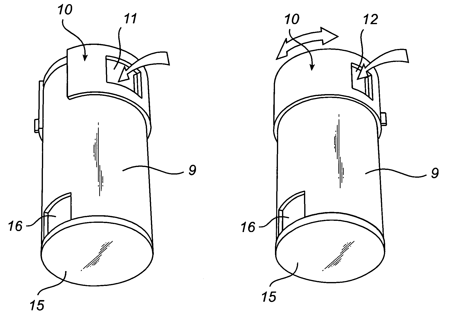
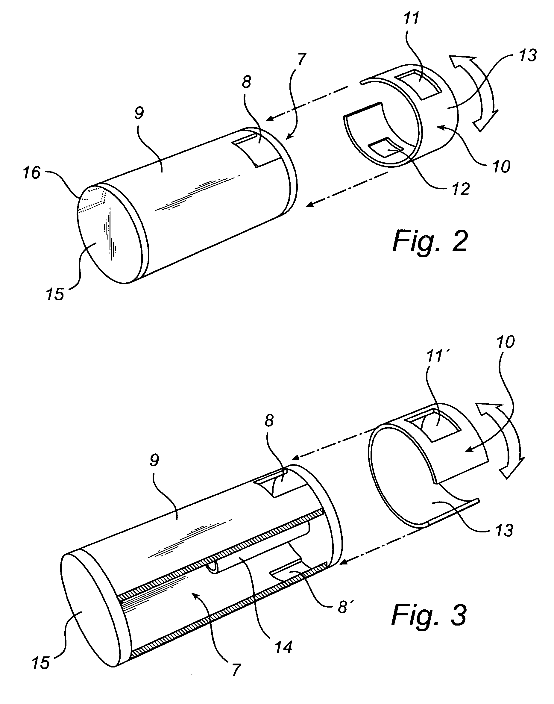
[0047]In FIG. 2, the cyclone-like separator 5 according to the invention is shown. The cyclone-like separator 5 is a cyclone separator which can be mounted in an air stream of a vacuum cleaner at any suitable position and any purpose which is suitable for the types of air streams that are available in this embodiment. The cyclone-like separator 5 has cyclone-like chamber in form of a cyclone chamber 7. The cyclone separator 5 comprises an air entrance device comprising a flow passage arrangement therethrough, wherein the flow passage arrangement includes an air inlet 8, which is provided in a wall surface 9 of the cyclone chamber 7.

[0048]The air entrance device further comprises a control member in the form of a valve member 10. The valve member 10 comprises a collar element 13, which is provided with a first opening 11 and a second opening 12. The first opening 11 is larger than the second opening 12, wherein the first opening 11 extends a greater distance along the circumference o...

second embodiment

[0056]In this embodiment, the control member is operable to alter the flow passage in that the collar element can be rotated such that in a first position, the first air inlet 8 is aligned with the opening 11′ and the second air inlet 8′ is closed by a portion of the collar element 13, and such that in a second position, the first air inlet 8 is closed by a portion of the collar element 13 and the second air inlet 8‘ is aligned with the opening 11’. Thus, by operating the valve member, the flow passage arrangement is affected such that the cyclone chamber 7 will receive an altered air stream, wherein the air stream is altered due to being introduced at a different location and due to having passed a narrower flow passage. The valve member 10 of the second embodiment is also an example of a control member which is operable to redirect an air stream from a first air inlet 8 to a second air inlet 8′, wherein the characteristic of the air stream is altered.

[0057]In FIGS. 5 and 6, third ...

third embodiment

[0059]In the embodiment according to FIG. 5, the control member comprises a pivotable flap 17. The flap 17 is operable to alter the entrance angle of an air stream passing through the air inlet, wherein, in addition, the angle of incidence of the air stream on the inner wall surface 9 of the cyclone chamber 7 is altered. Consequently, the control member 17 of this third embodiment is operable to alter the flow passage such that an air stream passing therethrough is affected.


PUM

PropertyMeasurementUnit
Angleaaaaaaaaaa
Flow rateaaaaaaaaaa
Electrical resistanceaaaaaaaaaa

Abstract

A cyclone separator for a vacuum cleaner. The separator has a cyclone chamber, an air entrance device having a flow passage arrangement therethrough for introducing an air stream into the cyclone chamber in a manner that causes the air stream to swirl in the cyclone chamber to remove dust from the air stream, and an air outlet for emitting the air stream from the cyclone chamber. The entrance device has a control member that is operable to alter the flow passage arrangement such that one or more properties of the air stream in the cyclone chamber are affected by the alteration. The flow passage arrangement has a first path and a second path, and the control member is operable to alter the flow passage arrangement by redirecting the air stream from the first path to the second path.

Description

FIELD OF THE INVENTION[0001]The present invention relates to a cyclone-like separator for a vacuum cleaner, wherein the cyclone-like separator is arranged to be mounted in an air stream of the vacuum cleaner. The present invention also relates to a vacuum cleaner and to a vacuum cleaner nozzle.BACKGROUND ART[0002]Generally, a vacuum cleaner draws a dust and debris containing air from a surface to be cleaned, separates at least some of the dust and debris from the drawn dust and debris containing air flow in a separating unit and releases an air flow relieved of the separated dust and debris to the surrounding air. Normally, the separated dust and debris is collected in the vacuum cleaner, for example in a compartment of the separating unit or in a separate compartment or container.[0003]One known separating unit for a vacuum cleaner is a filter bag, which is a bag made of a suitable filter material. The filter bag is placed in the air flow through the vacuum cleaner such that the ai...

Claims


Application Information

Patent Timeline
IPC IPC(8): A47L9/16B01D45/12B04C5/02
CPCA47L9/165B04C11/00B04C5/04
Inventor MIEFALK, HAKANLINDQUIST, TOMMYHAEGERMARCK, ANDERS
Owner AB ELECTROLUX
Why Eureka
Try Eureka