
Capacitive-inductive touch screen

Inactive Publication Date: 2010-12-30
STMICROELECTRONICS ASIA PACIFIC PTE
View PDF5 Cites 131 Cited by
  • Summary
  • Abstract
  • Description
  • Claims
  • Application Information

AI Technical Summary

Problems solved by technology

However, a resistive touch screen requires more pressure to activate the detection, a

Method used


Image

  • Capacitive-inductive touch screen
  • Capacitive-inductive touch screen
  • Capacitive-inductive touch screen

Examples


Embodiment Construction

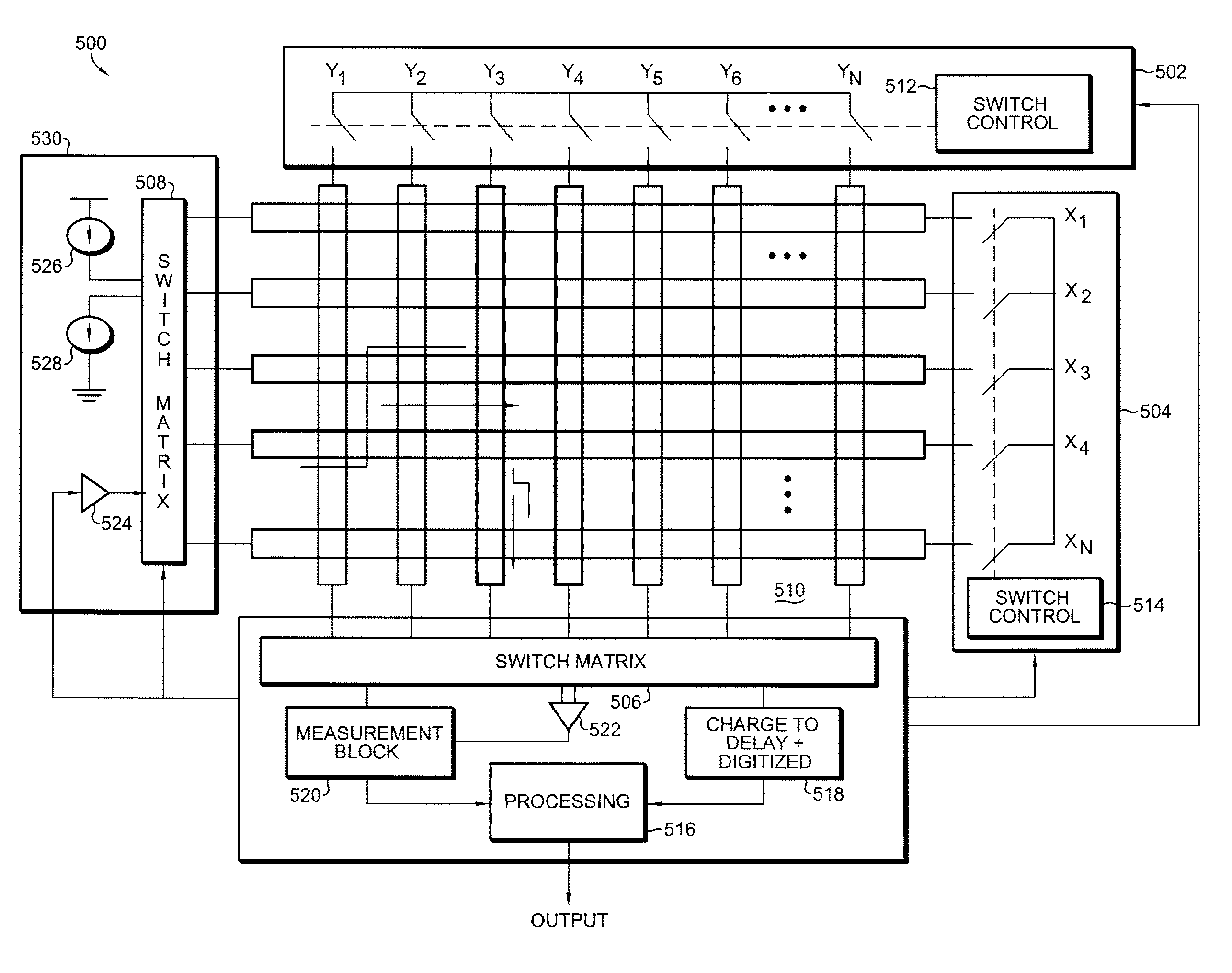
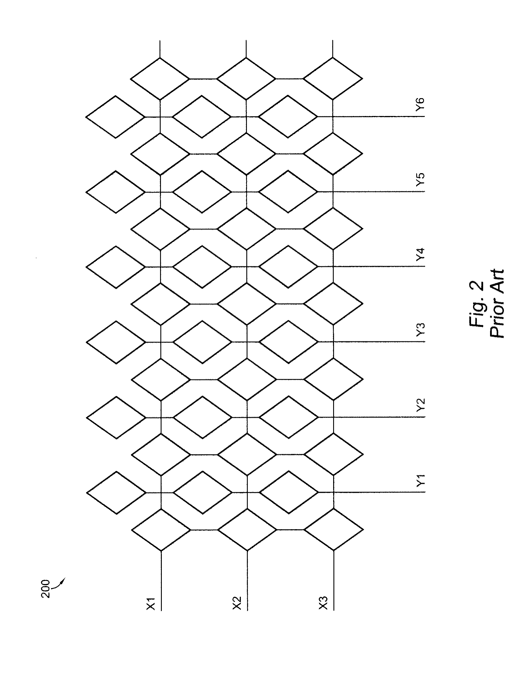
[0018]Referring now to FIG. 3, a portion 300 of a capacitive touch screen is shown, having a plurality of open loop X-lines X1-X4, and a plurality of open loop Y-lines Y1-Y6. A portion 302 of the touch screen is further highlighted where, for example, the third X-line crosses the fifth Y-line. The cross-capacitance between the two lines is shown in further detail. A multi-touch capacitive touch screen measures the cross-capacitance between the X-lines and the Y-lines. When a finger presses an intersection, the cross-capacitance is reduced. A charge amplifier is used to quantify the charge transferred by the cross-capacitance, and the value can be digitized.

[0019]Referring now to FIG. 4, a charge amplifier 400 is shown for use in conjunction with a capacitive touch screen or combination capacitive / inductive touch screen according to an embodiment of the present invention. Charge amplifier 400 includes a differential amplifier or operational amplifier 402 having a positive input for r...


PUM


Abstract

A touch screen uses a combination of capacitive sensing and inductive sensing applied to the same sensor pattern. A capacitive sensor uses the electric field formed by the columns and rows of the sensor matrix. An inductive sensor uses the magnetic field formed by current flowing in column and row lines to induce an inductive pen. Using the same sensor lines, the magnetic field created by the oscillating inductive pen is detected. Both methods require no moving elements in the sensor and it is possible to combine both method of detections in the same sensor pattern. Using switch matrices, the sensor lines are operated in an open loop fashion for the capacitive detection mode, and are operated in a closed loop fashion for the inductive detection mode.

Description

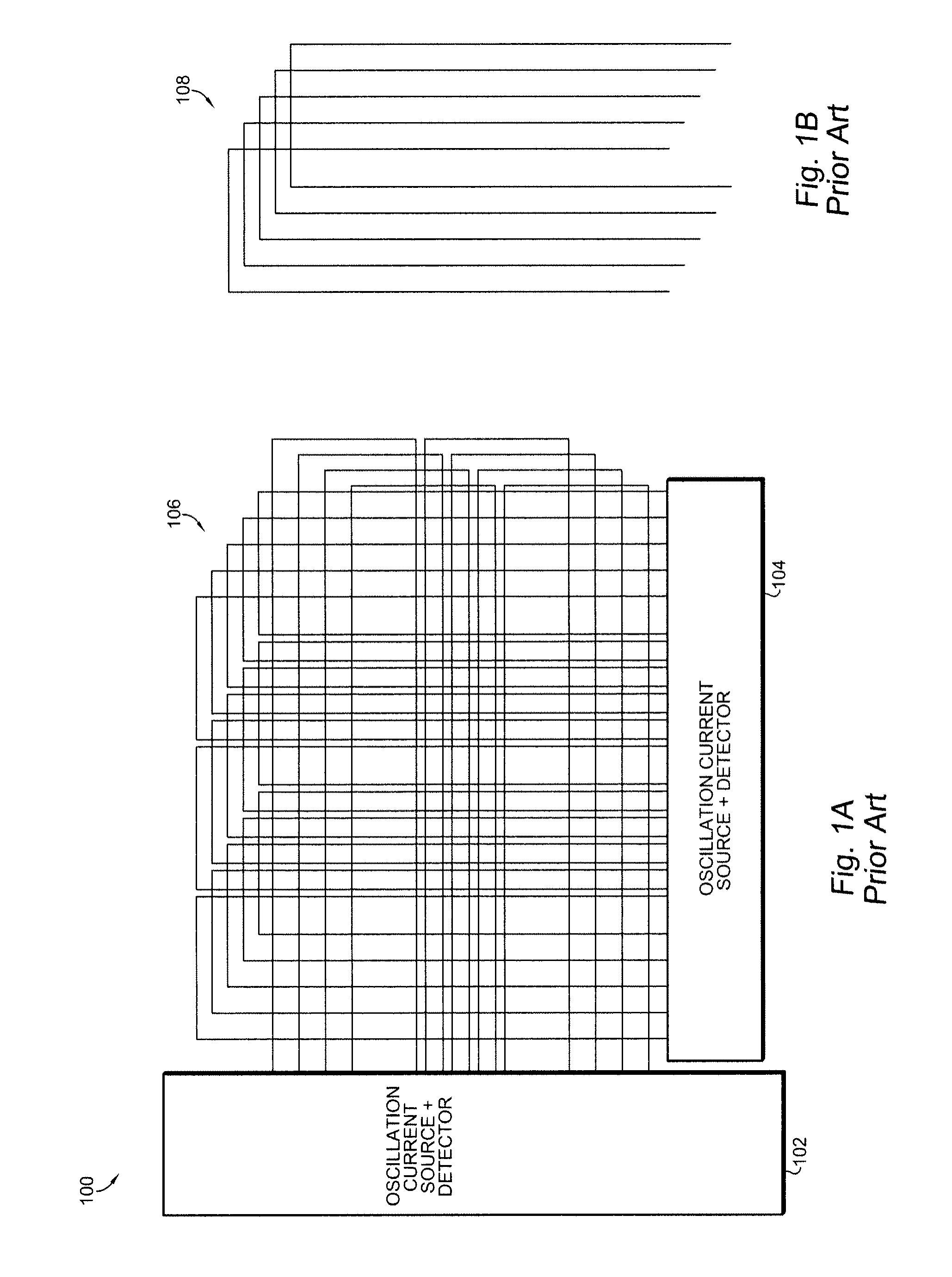
FIELD OF THE INVENTION[0001]The present invention is related to touch screens, and more particularly, to a touch screen that is capable of operating in a capacitive and inductive mode using the same sensor panel.BACKGROUND OF THE INVENTION[0002]A capacitive touch screen can only receive input from a finger, but it gives a different experience to the user and enables multi-touch inputs. A resistive touch screen is able to receive inputs from both a finger and a stylus. However, a resistive touch screen requires more pressure to activate the detection, and a traditional 4 / 5 / 8 wire resistive touch screen only allows one point of detection. Although a capacitive touch screen gives a better experience (sensitivity, multi-touch, and other advantages), some users still prefer to use a stylus, especially for hand-writing recognition application.[0003]A schematic of a prior art inductive touch screen 100 is shown in FIG. 1A. In the prior art, overlapped closed loop current lines 106 are used...

Claims


Application Information

Patent Timeline
IPC IPC(8): G06F3/044
CPCG06F3/046G06F3/044G06F3/0446G06F3/0447
Inventor NINGRAT, KUSUMA ADINOVIELLO, GIUSEPPEITALIA, FRANCESCO
Owner STMICROELECTRONICS ASIA PACIFIC PTE
Learn More