

Method for Object Localization Using Visual Images with Reference Coordinates
- Summary
- Abstract
- Description
- Claims
- Application Information
AI Technical Summary
Benefits of technology
Problems solved by technology
Method used
Image

Examples
Embodiment Construction
Technical Problem
[0005]The present invention provides a method of localizing an object by using visual images of reference coordinates, the method capable of improving accuracy and reducing the complexity of calculation.
Technical Solution
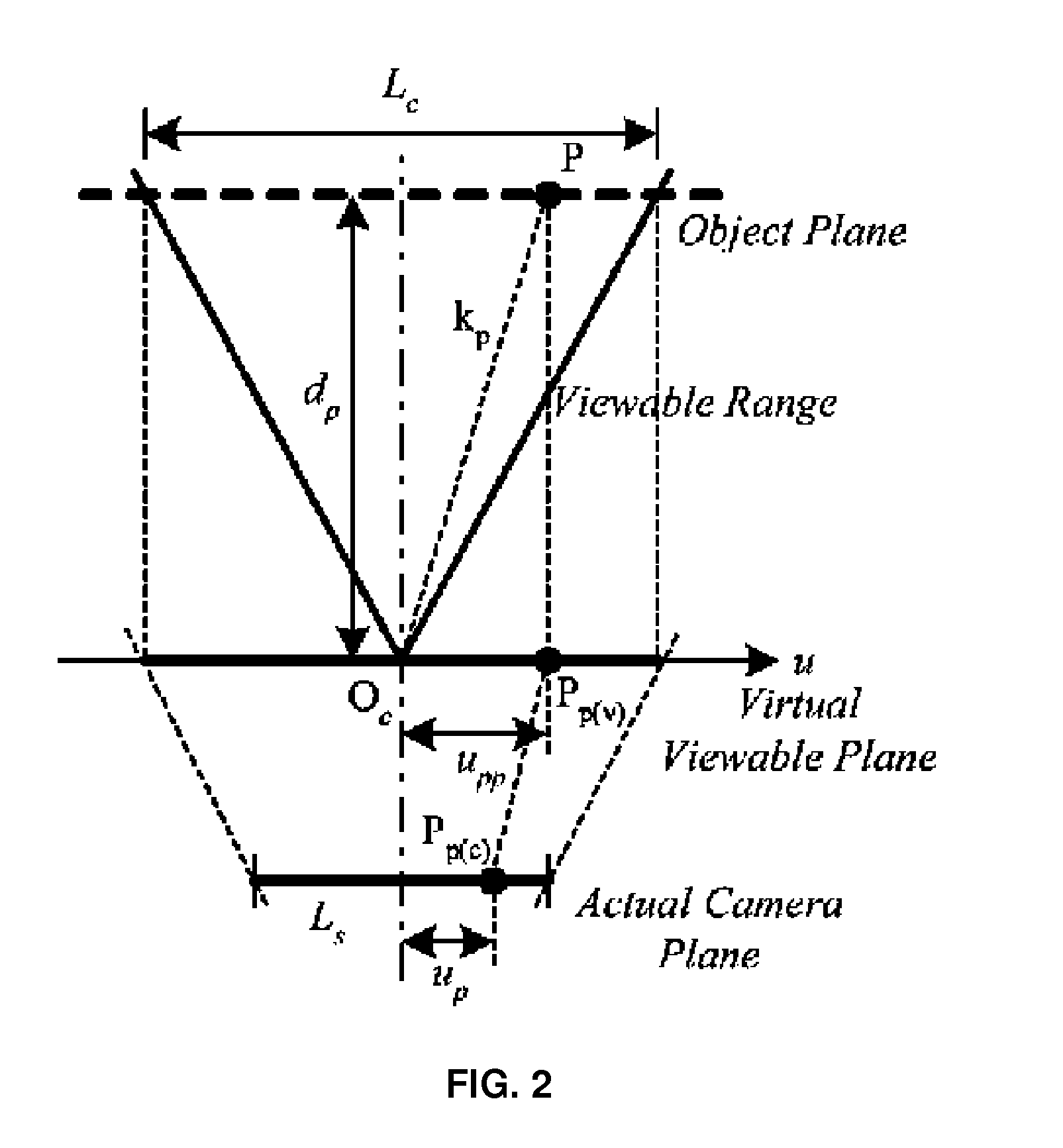
[0006]According to an aspect of the present invention, there is provided a method of localizing an object, the method including: projecting an object located on an object plane and a reference point corresponding thereto on a virtual viewable plane and an actual camera plane; estimating coordinates of the reference point; and prescribing a relationship between a location of the object and the coordinates of the reference point. Preferably, the virtual viewable plane may be parallel to the object plane. Preferably, the object may be projected by one sensor. On the other hand, the object may be projected by a plurality of sensors. When the object is projected by the plurality of sensors, the method may further include mutually compensating a differenc...
PUM
 Abstract
Description
Claims
Application Information