
Communication apparatus

Inactive Publication Date: 2010-12-30
BROTHER KOGYO KK
View PDF13 Cites 1 Cited by
  • Summary
  • Abstract
  • Description
  • Claims
  • Application Information

AI Technical Summary

Benefits of technology

[0006]However, in the above-described technique, where the number inputted by the user is not registered in the corporate telephone book database published on the network, the check of the inputted number cannot be performed unfortunately.
[0007]This invention has been developed in view of the above-described situations, and it is an object of the present invention to provide a communication apparatus which can reliably check whether a receiver apparatus is correct or not before data transmission, thereby preventing error transmission of data.

Problems solved by technology

However, in the above-described technique, where the number inputted by the user is not registered in the corporate telephone book database published on the network, the check of the inputted number cannot be performed unfortunately.

Method used


Image

  • Communication apparatus
  • Communication apparatus
  • Communication apparatus

Examples


first embodiment

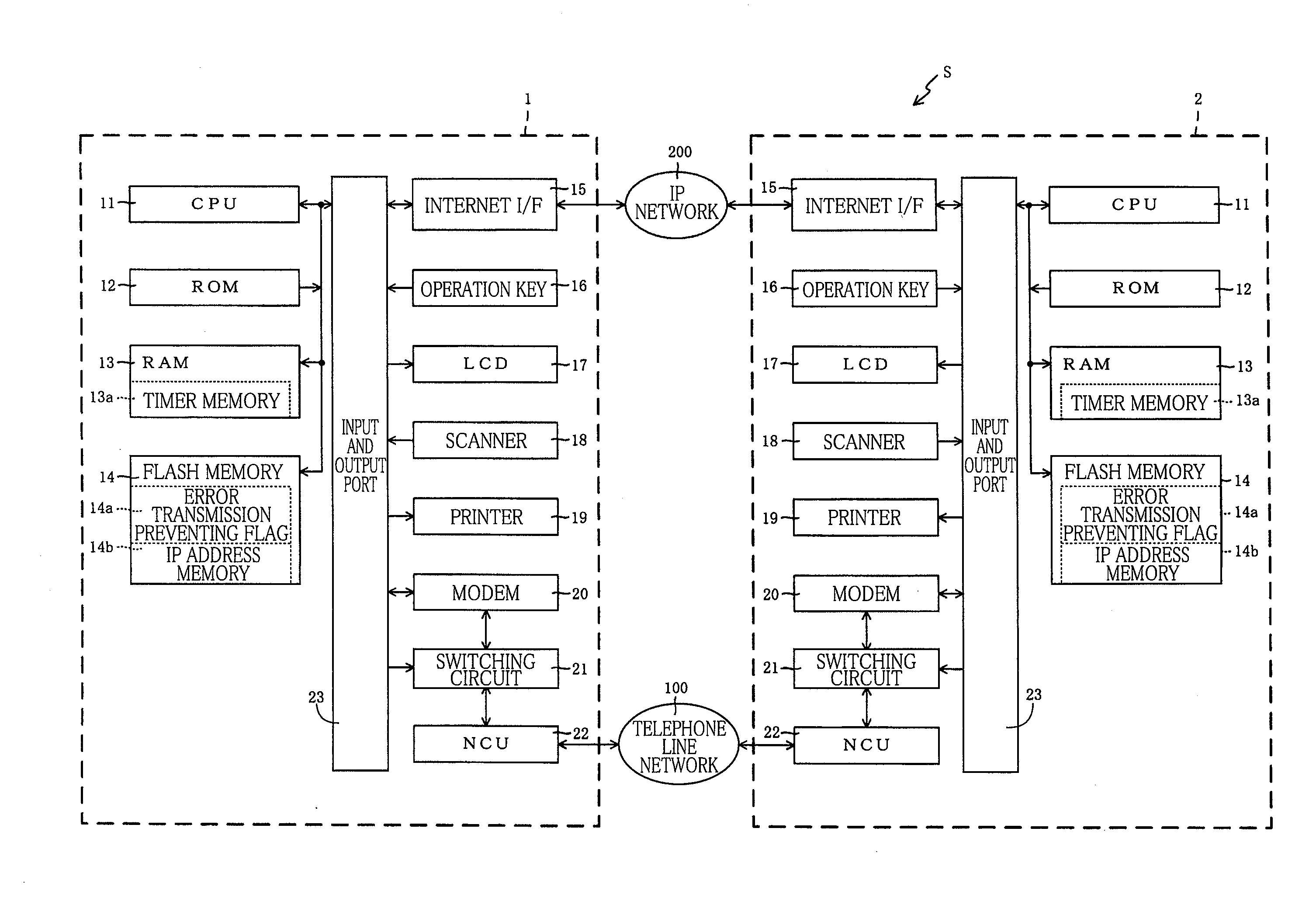
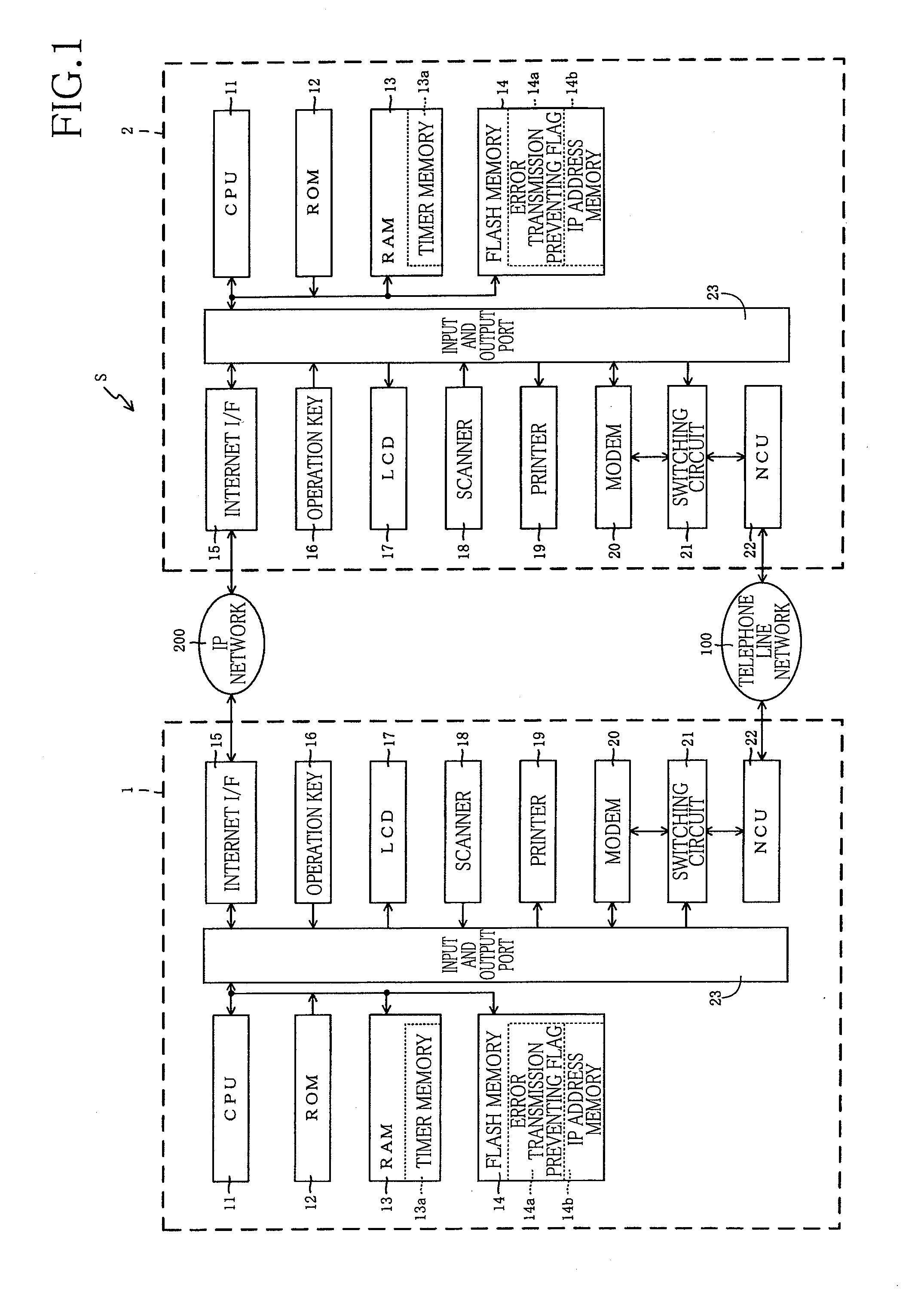
[0017]Hereinafter, there will be described embodiments of the present invention by reference to the drawings. A communication system S in the present first embodiment is constituted by a first facsimile apparatus 1 and a second facsimile apparatus 2 which can communicate with each other via a telephone line network 100 and an IP network 200.

[0018]The first facsimile apparatus 1 and the second facsimile apparatus 2 are the same apparatus, that is, have the same construction, and are configured to be capable of transmitting and receiving facsimile data. In the following explanation, the first facsimile apparatus 1 and the second facsimile apparatus 2 will be respectively referred to as a sender apparatus 1 and a receiver apparatus 2 for easy understanding purpose. However, since the sender apparatus 1 and the receiver apparatus 2 are the same apparatus, an explanation is given only for the sender apparatus 1, and the same reference numerals as used in the sender apparatus 1 are used t...

second embodiment

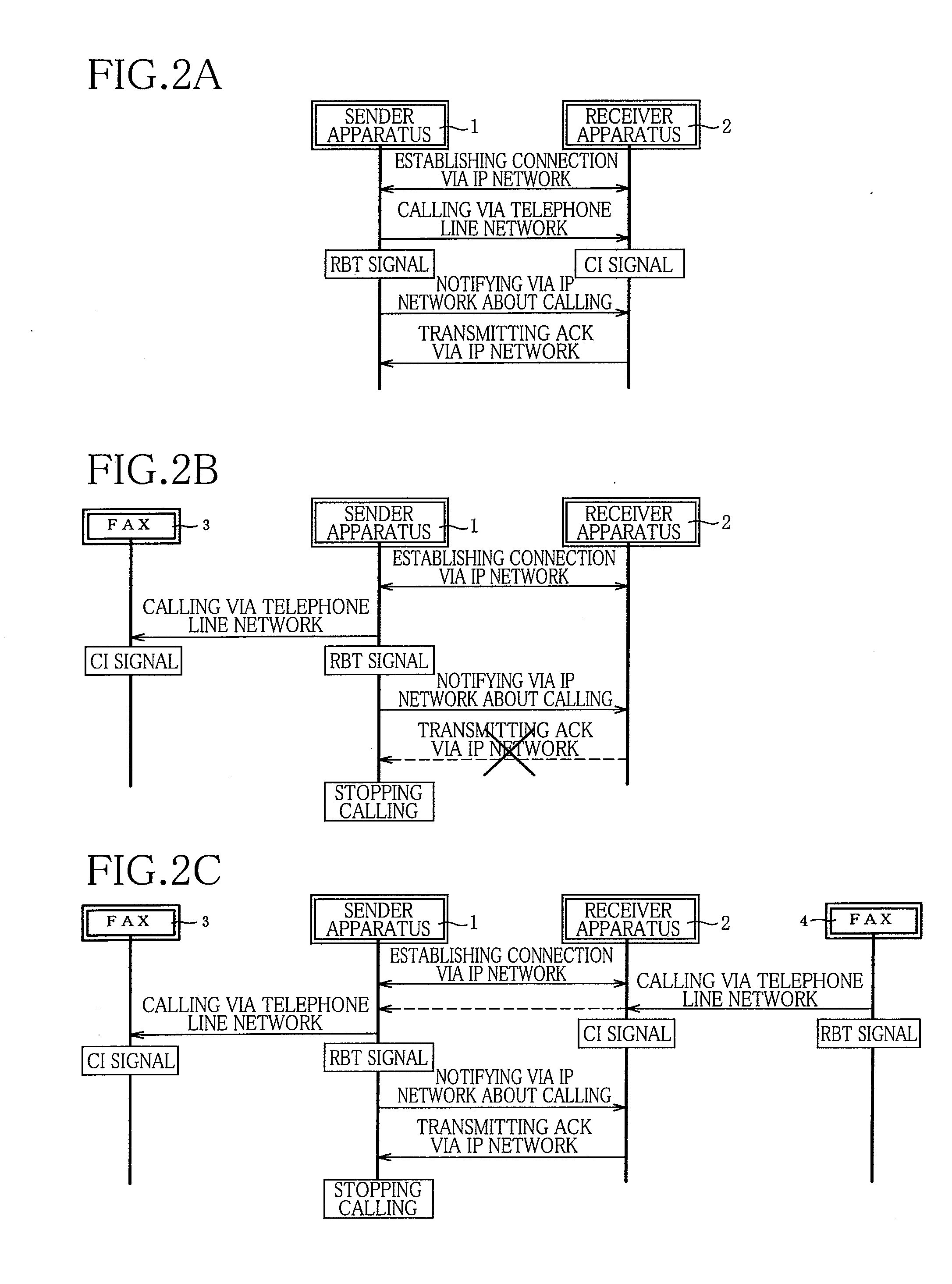
[0075]As thus described, according to this second embodiment, where the sender apparatus 1 has received the ACK from the receiving apparatus 2, the sender apparatus 1 can be considered to have reliably called the calling destination apparatus (i.e., the receiving apparatus 2). Thus, it is possible to prevent the error transmission of the facsimile data further reliably.

[0076]There will be next explained a FAX receiving processing in the second embodiment with reference to FIG. 7 which corresponds to FIG. 4. Here, only part of this second embodiment different from the first embodiment will be explained. It is noted that, in a flow-chart in FIG. 7, the same numerals as used in the first embodiment are respectively used for the same processings as in the flow-chart in FIG. 4. In this second embodiment, where the CPU 11 has detected the CI signal (S404: Yes), the receiver apparatus 2 receives in S701 the FAX number of the sender apparatus 1 via the telephone line network 100. Then, the ...


PUM


Abstract

A communication apparatus including: a requiring section which transmits a requirement for establishing a state in which and the communication apparatus and a first communication apparatus are communicable with each other via an internet line, to the first communication apparatus via the internet line; a communication establishing section which establishes the state; a calling section which transmits a dial signal to an exchanger via the telephone line and calls a to-be-called apparatus, when the communication establishing section has established the state; a notifying section which transmits a notification about calling of the communication apparatus, to the first communication apparatus via the internet line after the calling section has called; a receiving section which receives an acknowledgment signal transmitted via the internet line from the first communication apparatus having received the notification; and a communication controlling section which controls the communication with the to-be-called apparatus via the telephone line.

Description

CROSS REFERENCE TO RELATED APPLICATION[0001]The present application claims priority from Japanese Patent Application No. 2009-155620, which was filed on Jun. 30, 2009, the disclosure of which is herein incorporated by reference in its entirety.BACKGROUND OF THE INVENTION[0002]1. Field of the Invention[0003]The present invention relates to a communication apparatus.[0004]2. Description of the Related Art[0005]There is a technique that, before facsimile transmission, the number inputted by a user and a corporate telephone book database published on a network are verified, thereby checking whether the inputted number is correct or not.SUMMARY OF THE INVENTION[0006]However, in the above-described technique, where the number inputted by the user is not registered in the corporate telephone book database published on the network, the check of the inputted number cannot be performed unfortunately.[0007]This invention has been developed in view of the above-described situations, and it is a...

Claims


Application Information

Patent Timeline
IPC IPC(8): G06F3/12
CPCH04L12/40013H04N1/00214H04N1/0022H04N1/32702H04N2201/0039H04N1/32776H04N1/32797H04N2201/002H04N1/32765
Inventor ONO, HIROSHI
Owner BROTHER KOGYO KK
Learn More