Multi-phase resonant converter and method of controlling it

a multi-phase resonant converter and phase circuit technology, applied in the field of switching resonant voltage converters, can solve the problems of inactive phases, different currents in the various phase circuits, and serious obstacles to the implementation of “interleaving” techniques in multi-phase resonant voltage converters, and achieve good current balance

Active Publication Date: 2010-12-30
STMICROELECTRONICS SRL
View PDF18 Cites 63 Cited by
  • Summary
  • Abstract
  • Description
  • Claims
  • Application Information

AI Technical Summary

Benefits of technology

[0021]An architecture of multi-phase resonant converters has been found capable of maintaining a good balancing of the currents in each phase, even in the presence of relevant differences among the components

Problems solved by technology

One of the weak points of this architecture, especially when functioning at high power levels (>1 kW), is tied to the AC current that flows through the output capacitor COUT.
This is a serious obstacle to implementation of “interleaving” techniques in multi-phase resonant voltage converters.
As a consequence, the currents in the various phase circuits will differ, and one of them may even provide the whole power for the load, while the other phases may be inactive.
This situation, verified in an exemplary test case, is unacceptable because it would force to size each phase converter for delivering the whole output power, without any reduction of the ripple of the output current.
This architecture addresses the problem of balancing the currents at the cost of employing an additional conversion

Method used


Image

  • Multi-phase resonant converter and method of controlling it
  • Multi-phase resonant converter and method of controlling it
  • Multi-phase resonant converter and method of controlling it

Examples


Embodiment Construction

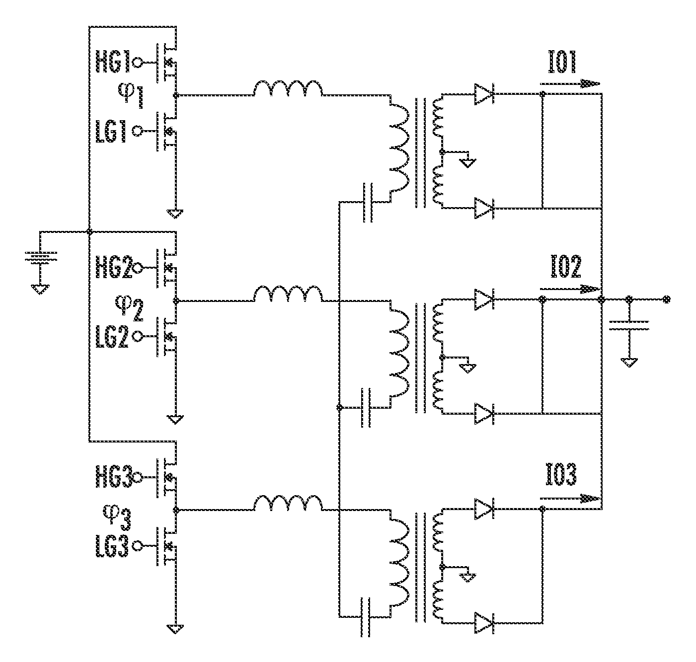
[0050]Several exemplary embodiments of this invention will be described making reference to a three-phase LLC resonant voltage converter, but the same considerations hold also for multi-phase resonant voltage converters of a different type and / or with any other number of phases.

[0051]A three-phase LLC resonant DC-DC voltage converter for limiting unbalance among phase currents is illustrated in FIG. 9. The three LLC resonant circuits on the primary side are connected to a floating common node (real neutral point) different from the prior art converter of FIG. 4 where the neutral point is grounded. The multi-phase resonant DC-DC voltage converter of this disclosure may be controlled using the same driving signals phased apart by 120° of the half-bridges of the prior art converter of FIG. 4.

[0052]The fact that the potential of the neutral-point is not grounded, introduces a “negative feedback” that tends to balance the working points of the single phase circuits, thus preventing a sin...


PUM


Abstract

A PWM controlled multi-phase resonant voltage converter may include a plurality of primary windings powered through respective half-bridges, and as many secondary windings connected to an output terminal of the converter and magnetically coupled to the respective primary windings. The primary or secondary windings may be connected such that a real or virtual neutral point is floating.

Description

FIELD OF THE INVENTION[0001]This invention relates to voltage converters and more particularly to switching resonant voltage converters.BACKGROUND OF THE INVENTION[0002]FIG. 1 is a high level block diagram of a switching resonant voltage converter. Among resonant voltage converters having the basic architecture of FIG. 1, and that are classified based upon the configuration of the resonant circuit that is used, there is the LLC resonant voltage converter. A half-bridge driven architecture of such a converter is illustrated in FIG. 2.[0003]For simplicity, reference will be made to half-bridge driven voltage converters, though the addressed technical problems also affect full-bridge driven voltage converters. One of the weak points of this architecture, especially when functioning at high power levels (>1 kW), is tied to the AC current that flows through the output capacitor COUT. This AC current has large peak and rms values that may require the use of a larger, and thus more encu...

Claims


Application Information

Patent Timeline
IPC IPC(8): H02M3/335
CPCH02M3/335Y02B70/1433H02M3/33569Y02B70/10H02M3/33571H02M3/33573H02M3/01
Inventor ADRAGNA, CLAUDIOGATTAVARI, GIUSEPPEMATTAVELLI, PAOLOORIETTI, ENRICOSPIAZZI, GIORGIO
Owner STMICROELECTRONICS SRL
Why Eureka
Try Eureka