Specimen Holder For A High-Pressure Freezing Device

a high-pressure freezing and specimen technology, applied in the direction of heating types, containers, internal frames, etc., can solve the problems of inability to predict which sample regions will be usable and which will be unusable, and the sample cannot be used

Active Publication Date: 2011-01-06
LEICA MICROSYSTEMS GMBH
View PDF6 Cites 4 Cited by
  • Summary
  • Abstract
  • Description
  • Claims
  • Application Information

AI Technical Summary

Benefits of technology

The technical effect of this patent is that it eliminates the use of difficult or time-consuming screw couplings by allowing two parts to be pushed together in a clamming device. This makes it easier to work with smaller containers and reduces the risk of mistakes during assembly.

Problems solved by technology

The technical problem addressed in this patent is the permeability of sample tubes during high-pressure freezing of biological samples using liquid nitrogen as a cryogen. This can result in the sample becoming unusable due to the formation of large crystals of hexagonal ice I in the middle of sample regions that exhibit vitreous or microcrystalline frozen sample regions. The patent aims to reduce this permeability and improve the overall quality of the cryopreserved samples.

Method used


Image

  • Specimen Holder For A High-Pressure Freezing Device
  • Specimen Holder For A High-Pressure Freezing Device

Examples


Embodiment Construction

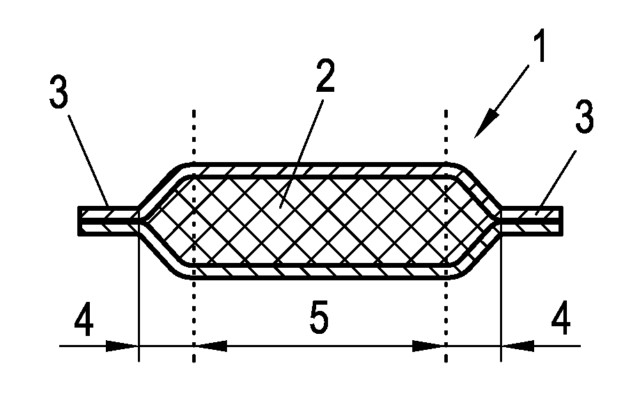
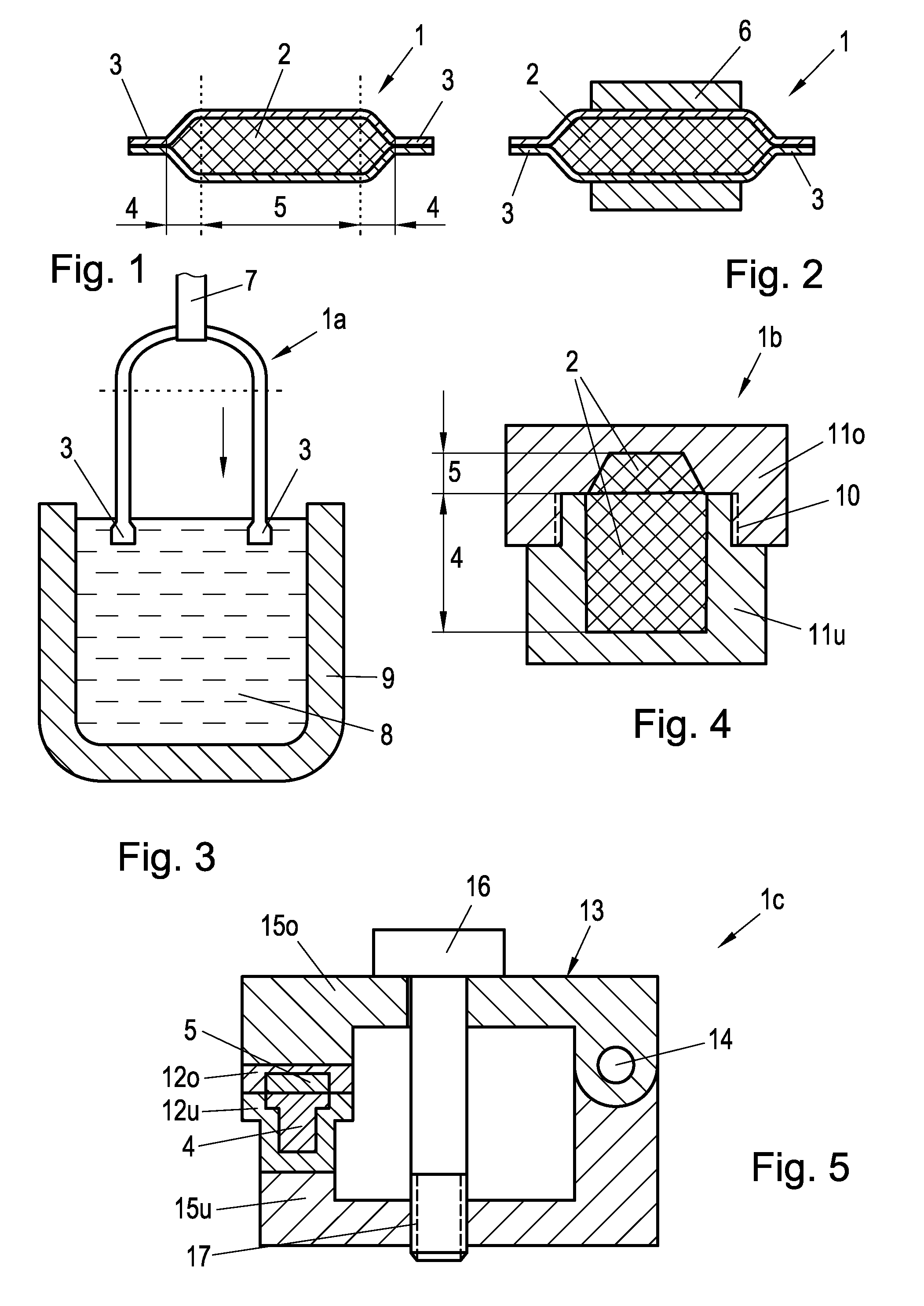
[0026]FIG. 1 shows a tubular sample container 1, which may be used for single cells or small organisms such as nematodes, for example, and is formed from a capillary tube. At an outside diameter of 0.6 mm and an inside diameter of 0.3 mm, an exemplary specific embodiment of such a sample container is 16 mm long, for example. Once the sample container is filled with a hydrous biological sample, which then forms container contents 2, the container made of copper, for example, is firmly sealed at ends 3 thereof, for example, pinched over a length of approximately 1 mm, using pliers

[0027]Subsequently thereto, the container is initially cooled at both ends 3 thereof, and the remainder of the container is then cooled, so that the entire container contents solidify. It is clear that there are no clear transitions here due to the thermal conductivity of the container wall. However, in the present case, particularly when working with a tubular container 1 having pinched ends, the advantage i...


PUM


Abstract

A method for preparing a hydrous, cryopreserved sample that is enclosed in a sample container (1, 1a, 1b, 1c), in the case of which, at least sample material is introduced into the sample container; this is then sealed pressure-tight and subsequently cooled by a cryogen (8) in a temporal and spatial sequence, a sacrificial region (4) of the container contents (2) initially solidifying and, only subsequently thereto, the entire container contents solidifying. A sample container (1a) that may be preferably used in this case is designed to be tubular, sealed at both ends thereof, and to essentially have a U-shaped form.

Description


Claims


Application Information

Patent Timeline
Owner LEICA MICROSYSTEMS GMBH
Why Eureka
Try Eureka